Aeration-less water treatment apparatus

a technology of water treatment apparatus and water treatment chamber, which is applied in the direction of multi-stage water/sewage treatment, filtration separation, separation process, etc., can solve the problems of degrading affecting the quality of inflow sewage, and increasing the amount of organic polluted matter, etc., to achieve stable quality

Inactive Publication Date: 2009-02-05
KK TOSHIBA
View PDF20 Cites 23 Cited by
  • Summary
  • Abstract
  • Description
  • Claims
  • Application Information

AI Technical Summary

Benefits of technology

[0019]The present invention has been made to solve the above-described problems. An object of the present invention is to provide an aeration-less water treatment apparatus which, when subjected to any of various variations and disturbances during a trea

Problems solved by technology

However, during a treatment operation performed by the conventional apparatus, various variations and disturbances described below may occur.
(2) Degraded quality of inflow sewage (increase in the amount of organic polluted matter)
This may result in problems (i) to (iii).
(iii) Degraded quality of treated water
However, if (1) the increased amount of inflow of sewage increases the velocity of the upward flow 1

Method used


Image

  • Aeration-less water treatment apparatus
  • Aeration-less water treatment apparatus
  • Aeration-less water treatment apparatus

Examples


first embodiment

[0059]In the present embodiment, an aspect will be described in which an aeration-less water treatment apparatus according to the present invention is used for a sewage treatment facility.

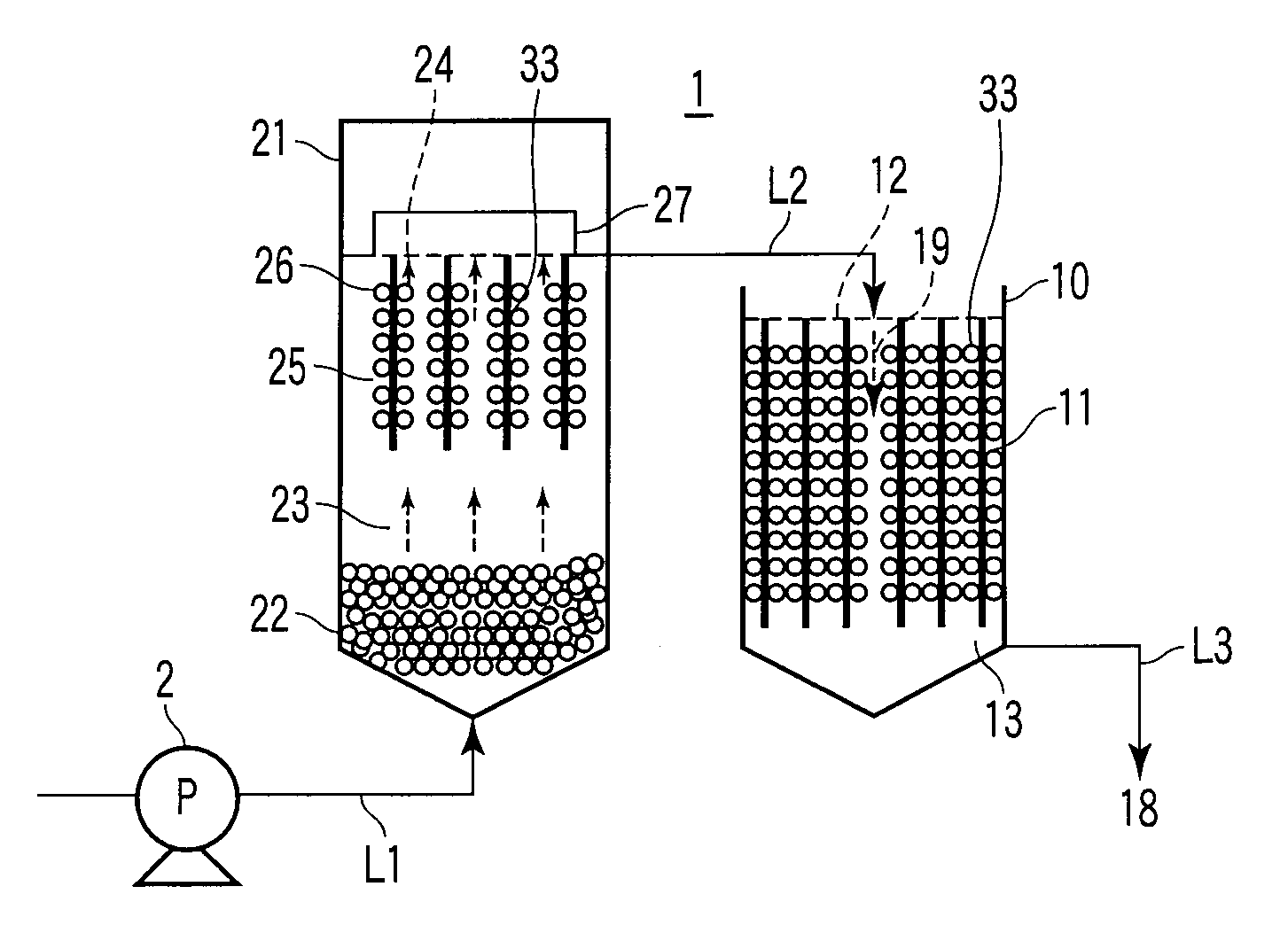
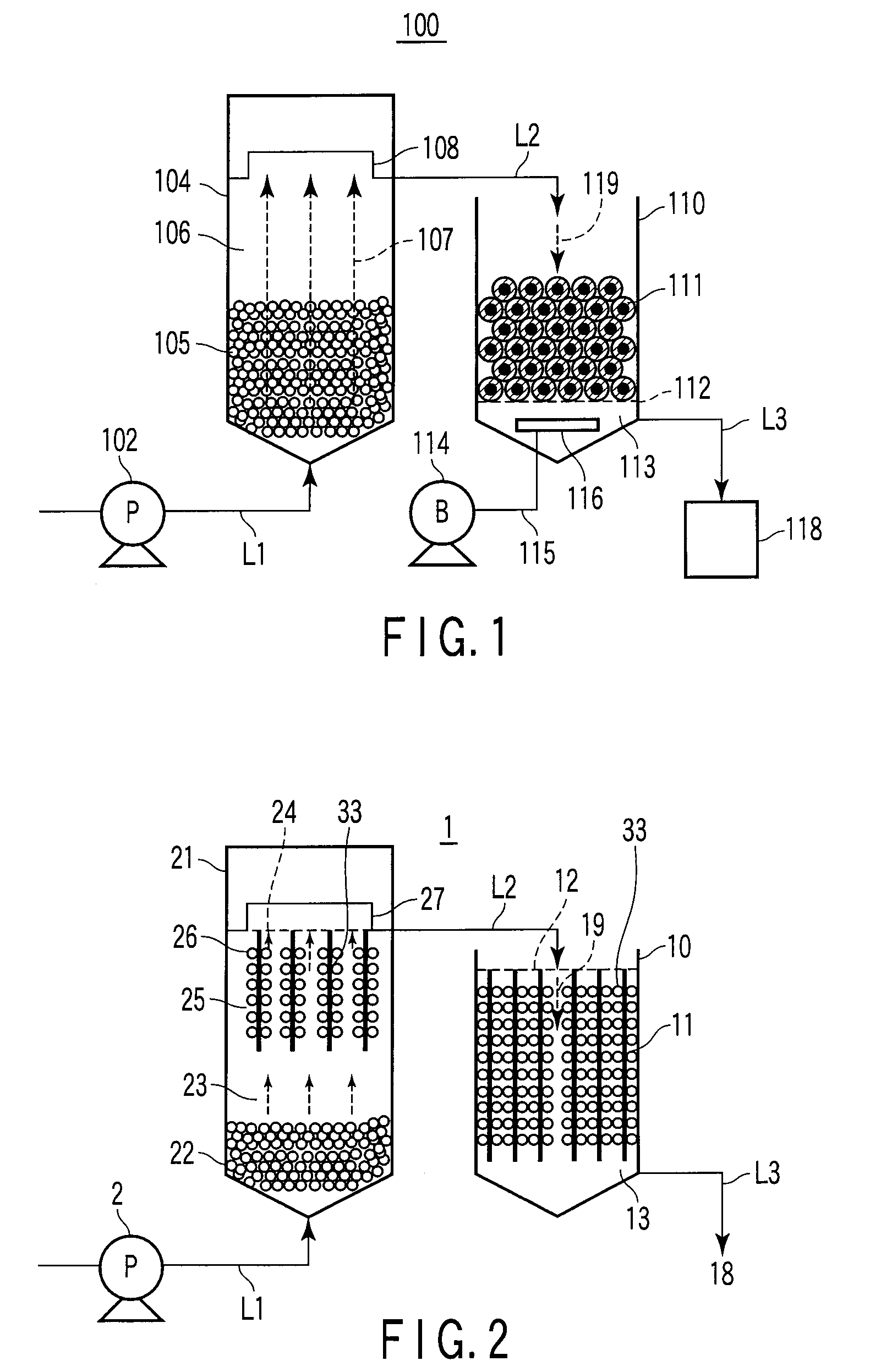
[0060]As shown in FIG. 2, an aeration-less water treatment apparatus1 comprises an anaerobic reactor 21 in a first stage and an aerobic reactor 10 in a second stage. An ejection port of a pump 2 is connected to the bottom of the anaerobic reactor 21 via a supply line L1. Waste water from a waste water source (not shown) is drivingly introduced into the anaerobic reactor 21 from below by means of the pump 2. The top of the anaerobic reactor 21 and the top of the aerobic reactor 10 are connected together by an overflow line L2. A cover is installed over an upper opening in the anaerobic reactor 21. A maintenance worker can open the cover to maintain and inspect the interior of the anaerobic reactor 21. An upper opening in the aerobic reactor 10 is open to the atmosphere.

[0061]The anaerobic reactor 21...

second embodiment

[0094](1) Filling Factor of the Anaerobic Microorganism-Adhering Carrier Section 25

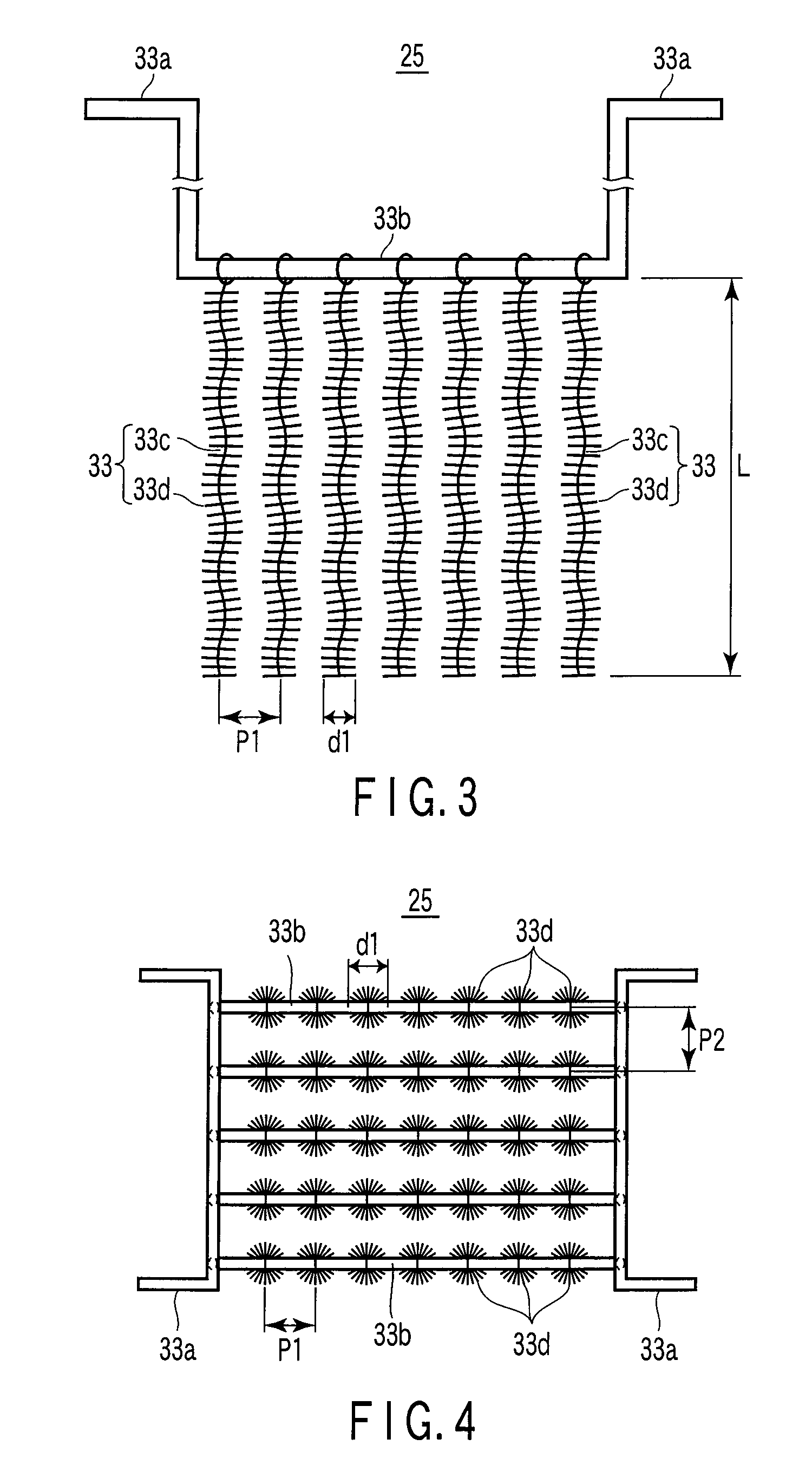
[0095]The anaerobic microorganism-adhering carrier section 25 according to the second embodiment, to which the anaerobic microorganisms in UASB are attached and fixed, are module fillers each made of plastics and having any of various shapes or forms including a cylinder, a sphere, an oval sphere, a cubic, a rectangular parallelepiped, a polyhedra, and a spiral. The carriers are supported by the carrier support section 24.

[0096]In the apparatus 1 according to the first embodiment, the filling factor of the anaerobic microorganism-adhering carrier section 25 is about 20% of the effective volume (the actual volume of water in the anaerobic reactor 21). However, according to the present invention, the filling factor of the carrier section 25 is not limited to this aspect. In an apparatus 1A according to the present embodiment, as shown in FIG. 9, for example, the filling factor of the carrier section 25 ...

third embodiment

[0099](2) Structure Inhibiting Upward Outflow from the Anaerobic Microorganism-Adhering Carrier Section 25

[0100]In the apparatus 1 according to the first embodiment, the second supernatant section 26 and the overflow section 27 are provided above the anaerobic microorganism-adhering carrier section 25. However, according to the present invention, the upper structure of the anaerobic reactor is not limited to this aspect. If the aggregate of the anaerobic microorganisms floating up from the suspended sludge section 22, located below the carrier section, excessively adheres excessively to the surfaces of the carriers in the carrier section 25 to reduce the specific gravity of each of the carriers, the carriers may float up.

[0101]Thus, in the aeration-less water treatment apparatus according to the present embodiment, a stopper is provide above the carrier section to stop the carriers floating up owing to the reduced specific gravity of each of the carriers. For example, in an aeration...


PUM

PropertyMeasurementUnit
Grain sizeaaaaaaaaaa
Flow rateaaaaaaaaaa
Shapeaaaaaaaaaa

Abstract

An aeration-less water treatment apparatus including an anaerobic reactor which receives sewage to cause the sewage to flow as an upward stream, and an aerobic reactor which receives treated water from the anaerobic reactor to cause the water to flow as a downward stream so that the water contacts aerobic microorganisms and air to aerobically treat the polluted matter in the water, the apparatus further including a suspended sludge section located in a lower part of the anaerobic reactor and in which the anaerobic microorganisms are suspended in the sewage, and a carrier section located in an upper part of the anaerobic reactor and having carriers to which the anaerobic microorganisms are attached, the anaerobic microorganisms having flowed from the suspended sludge section being further attached to the carriers.

Description

CROSS-REFERENCE TO RELATED APPLICATIONS[0001]This application is based upon and claims the benefit of priority from prior Japanese Patent Application No. 2007-176571, filed Jul. 4, 2007, the entire contents of which are incorporated herein by reference.BACKGROUND OF THE INVENTION[0002]1. Field of the Invention[0003]The present invention relates to an aeration-less water treatment apparatus that performs a purifying treatment on waste water such as urban sewage, industrial liquid waste, and household liquid waste using microorganisms.[0004]2. Description of the Related Art[0005]JPA KOKAI Publication No. 11-285696 proposes an aeration-less water treatment apparatus utilizing anaerobic and aerobic microorganisms, as means for performing a purifying treatment on sewage. As shown in FIG. 1, in a conventional apparatus 100, sewage is drivingly introduced into an anaerobic reactor 104 through a line L1 by means of a pump 102. The anaerobic reactor 104 comprises an up flow anaerobic sludge ...

Claims


Application Information

Patent Timeline
IPC IPC(8): C02F3/30
CPCC02F3/04C02F3/103Y10S210/903C02F3/2846C02F3/30C02F3/2806Y02W10/10
Inventor TSUTSUMI, MASAHIKOOBARA, TAKUMIASHIKAGA, NOBUYUKIYAMAMOTO, KATSUYATAMURA, HIROSHI
Owner KK TOSHIBA
Why Eureka
Try Eureka