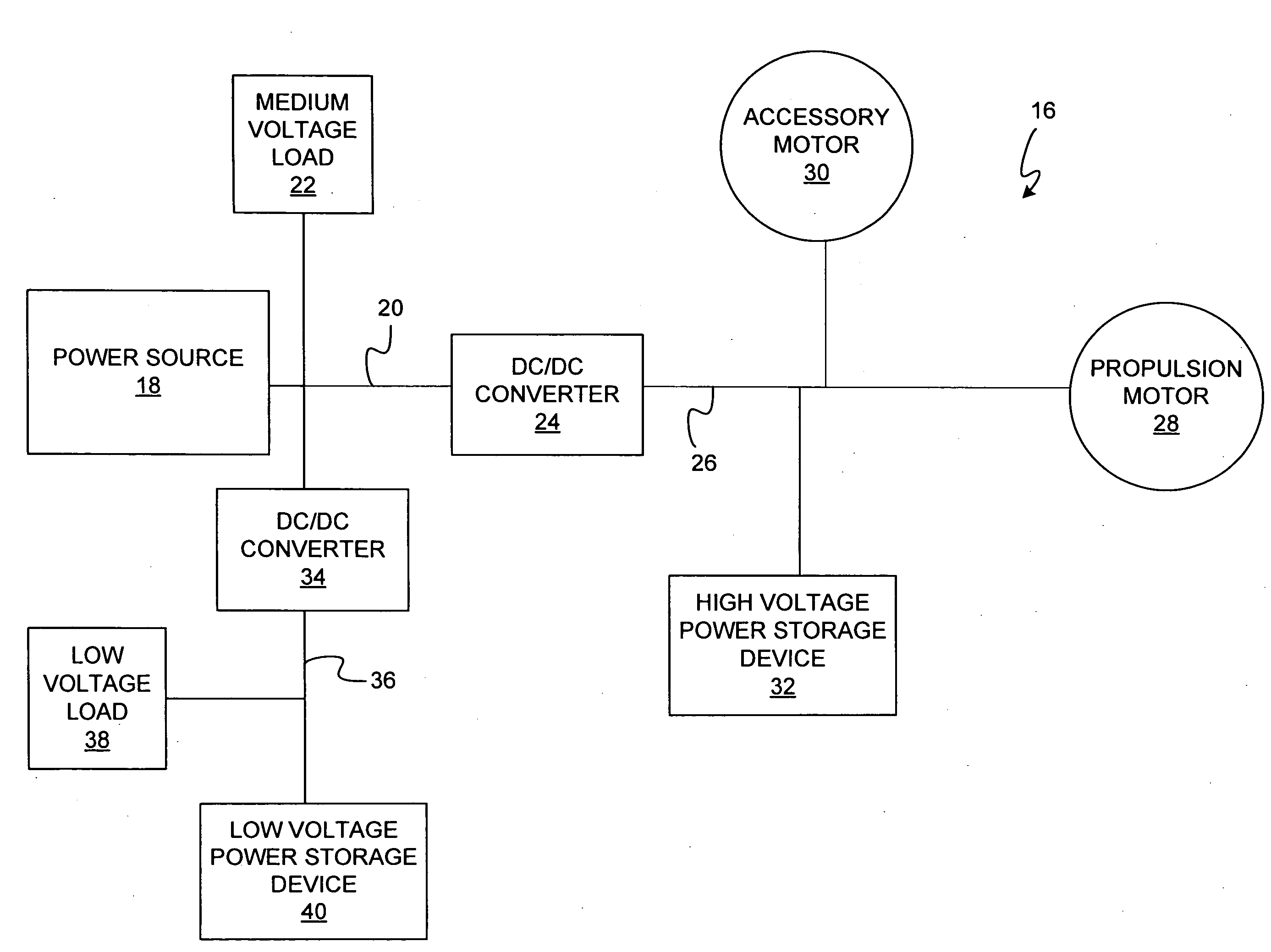
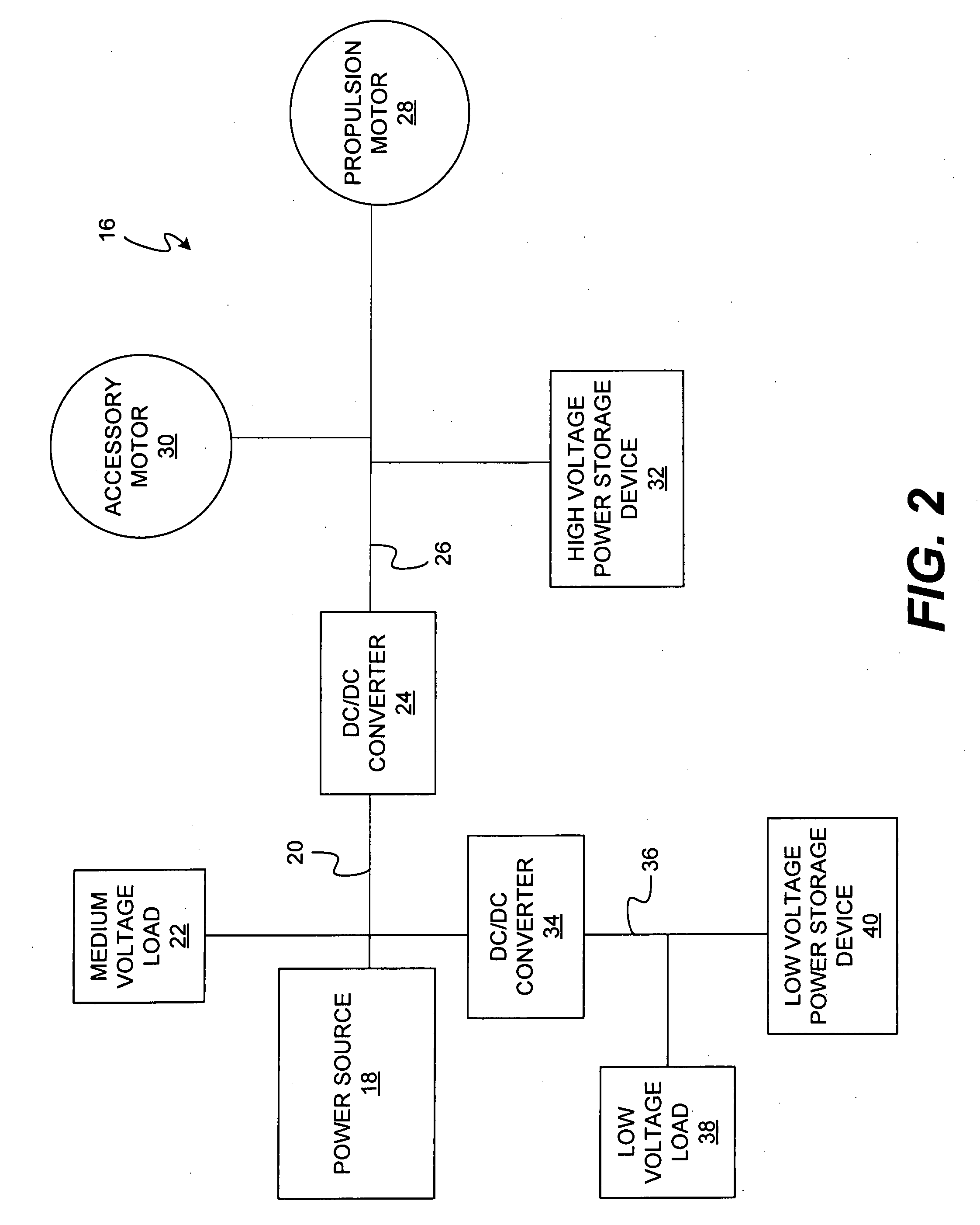
Electrical system architecture having high voltage bus
a technology of electric system and bus, which is applied in the direction of auxiliary energy regeneration, transportation and packaging, electric devices, etc., can solve the problems of equipment downtime, unnecessarily limited options for changing propulsion motors and/or accessory motors, and limited dc voltage to the main bus
- Summary
- Abstract
- Description
- Claims
- Application Information
AI Technical Summary
Benefits of technology
Problems solved by technology
Method used
Image

Examples
Embodiment Construction
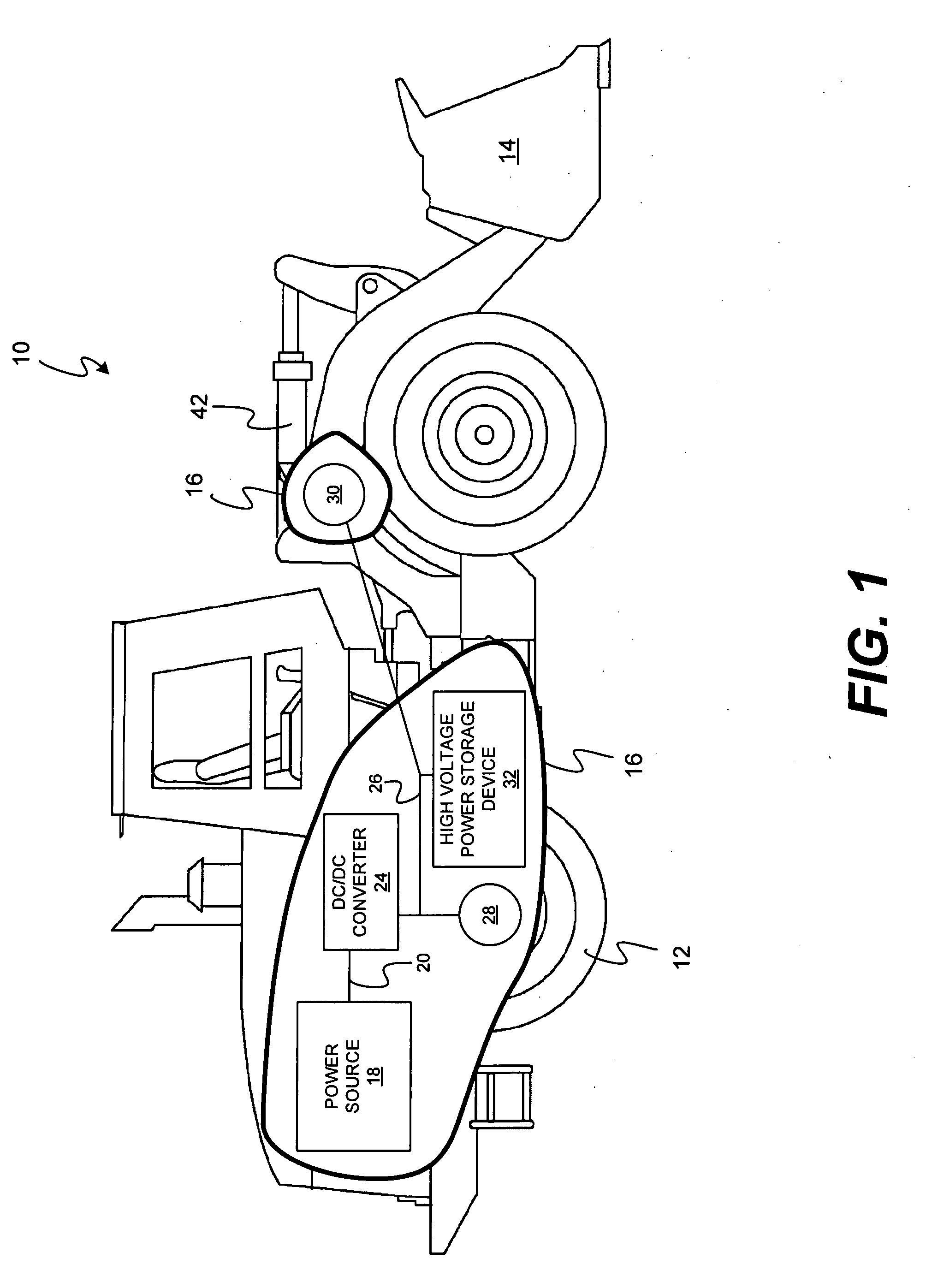
[0016]FIG. 1 illustrates an exemplary hybrid machine 10. Although hybrid machine 10 is illustrated as a wheel loader, it is contemplated that hybrid machine 10 may embody any mobile hybrid machine. For example, hybrid machine 10 may be an earth moving machine such as a dozer, a backhoe, an excavator, a motor grader, or any other earth moving machine. It is contemplated that hybrid machine 10 may alternatively embody any other type of mobile hybrid machine 10 such as, for example, a hybrid automobile. Hybrid machine 10 may include a traction device 12, an accessory 14, and an electrical system architecture 16 to provide power to traction device 12, accessory 14, and / or other components of hybrid machine 10.
[0017]Traction device 12 may embody one or more wheels located on each side of hybrid machine 10. It is contemplated that traction device 12 may additionally or alternatively embody one or more tracks, belts, and / or any other device for maneuvering hybrid machine 10. Traction devic...
PUM
 Abstract
Description
Claims
Application Information
 - R&D
- Intellectual Property
- Life Sciences
- Materials
- Tech Scout
- Unparalleled Data Quality
- Higher Quality Content
- 60% Fewer Hallucinations
Browse by: Latest US Patents, China's latest patents, Technical Efficacy Thesaurus, Application Domain, Technology Topic, Popular Technical Reports.
© 2025 PatSnap. All rights reserved.Legal|Privacy policy|Modern Slavery Act Transparency Statement|Sitemap|About US| Contact US: help@patsnap.com