
Voltage conversion device

Inactive Publication Date: 2009-02-05
TOYOTA JIDOSHA KK
View PDF1 Cites 12 Cited by
  • Summary
  • Abstract
  • Description
  • Claims
  • Application Information

AI Technical Summary

Benefits of technology

[0013]According to the present invention, since the rate of change is set corresponding to the magnitude of the voltage command value, a high control response capability can be attained as compared to a conventional control circuit in which a rate of change is set based on an output voltage of a voltage converter. In addition, since a tracking capability of the output voltage of the voltage converter for the voltage command value is ensured, overshooting of the output voltage can be suppressed.
[0015]Therefore, according to the present invention, since the capacity element can be protected from overshooting of the output voltage, a margin is not required to be provided to a rated voltage of the capacity element, and a capacity of the capacity element can be decreased.
[0017]Therefore, according to the present invention, since the rate of change is decreased in response to the voltage command value going beyond the threshold value, overshooting of the output voltage can be suppressed by ensuring the tracking capability of the output voltage of the voltage converter for the voltage command value, and a response period of the load can be prevented from delaying.
[0019]Therefore, according to the present invention, the load can be protected from an overvoltage due to overshooting of the output voltage.
[0020]According to the present invention, since the rate of change of the voltage command value between control timings is set corresponding to the magnitude of the voltage command value, a high control response capability can be attained as compared to the conventional control circuit in which a rate of change of a voltage command value is controlled using an output voltage of a voltage converter. Therefore, the tracking capability of the output voltage of the voltage converter for the voltage command value can be ensured until the output voltage reaches the target voltage, and thus overshooting of the output voltage can be suppressed.
[0021]Furthermore, since a period required for the output voltage to reach the target voltage can be accurately determined, a response period to the load can be managed and a high response capability for the load can be maintained.

Problems solved by technology

Therefore, when the voltage command abruptly changes in response to a sudden variation in a load, a control response capability sufficient to handle such change cannot be maintained.
In this situation, overshooting of the output voltage of the chopper circuit may occur due to a delay in the control response capability.
Therefore, overshooting cannot be reliably prevented.
Therefore, management of a response period of motor control may not be possible.

Method used


Image

  • Voltage conversion device
  • Voltage conversion device
  • Voltage conversion device

Examples


Embodiment Construction

[0031]An embodiment of the present invention will now be described in detail referring to the drawings. It is to be noted that, the same characters in the drawings Indicate the same or corresponding portions.

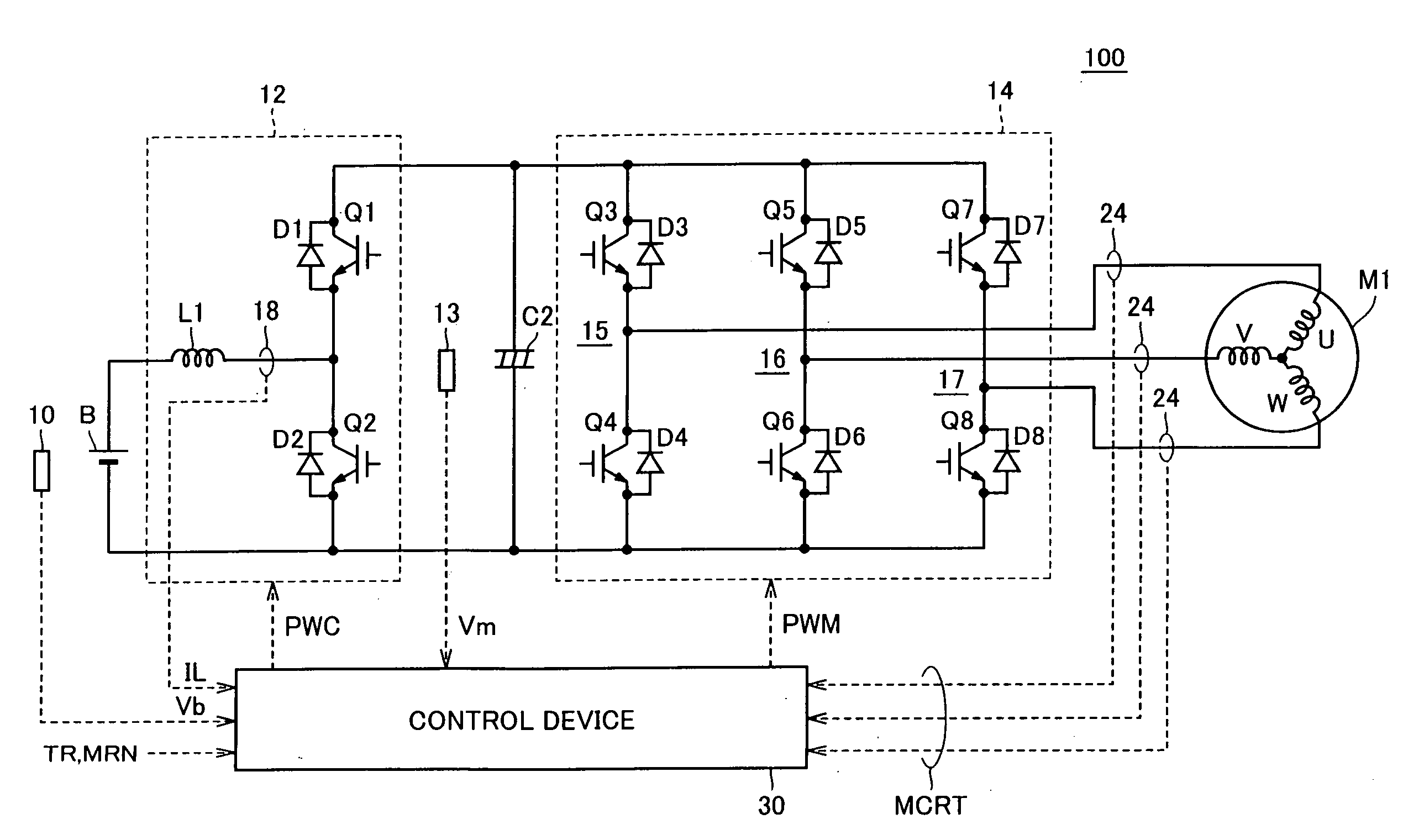
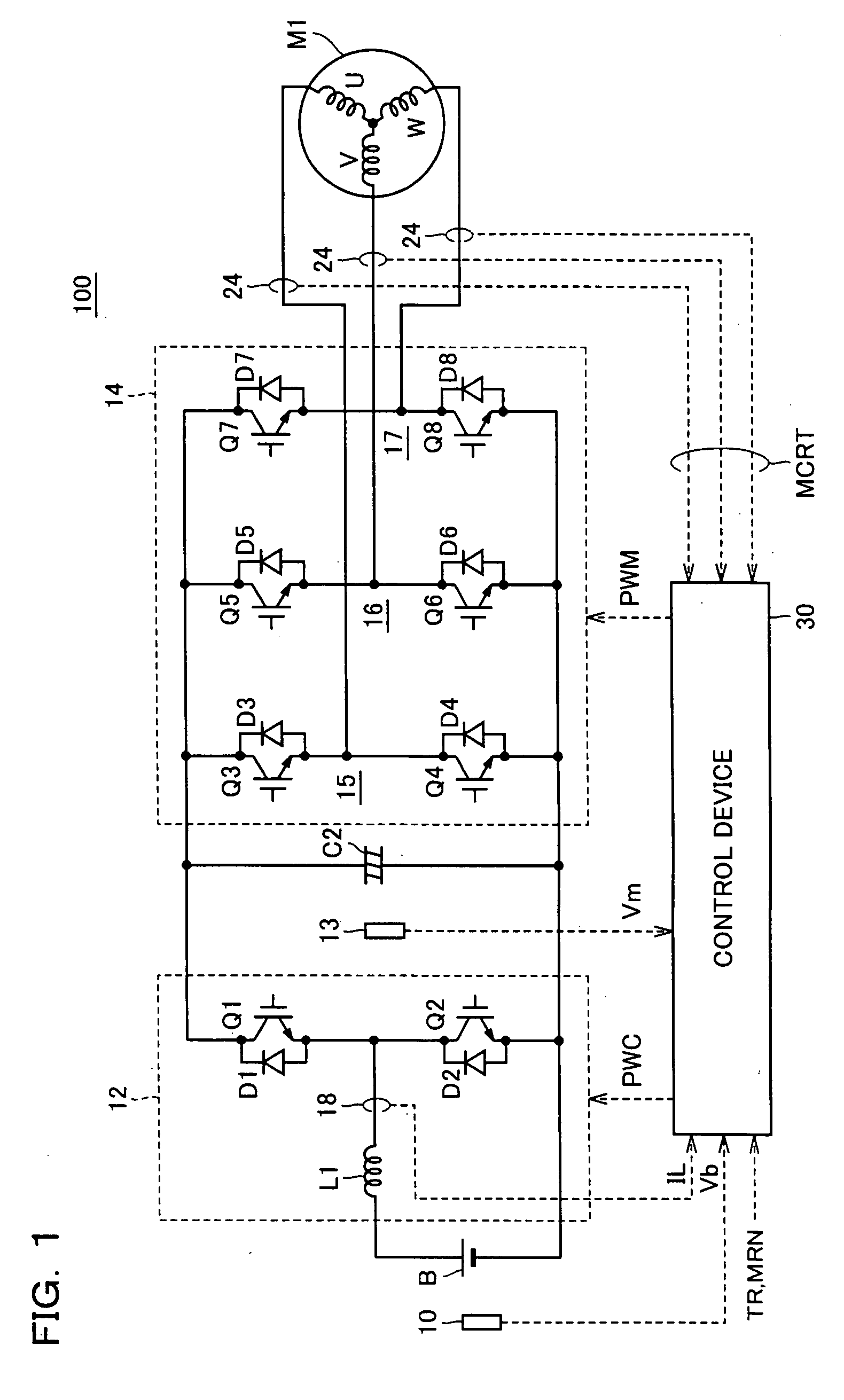
[0032]FIG. 1 is a schematic block diagram of a motor drive device to which a voltage conversion device according to the embodiment of the present invention is applied.

[0033]Referring to FIG. 1, a motor drive device 100 includes a DC power supply B, voltage sensors 10, 13, current sensors 18, 24, a capacitor C2, a boost converter 12, an inverter 14, and a control device 30.

[0034]An AC motor M1 is a drive motor for generating a torque for driving a driving wheel of a hybrid vehicle or an electric vehicle. AC motor M1 also has a function of a generator driven by an engine, and can operate as an electric motor for the engine to perform, for example, starting of the engine.

[0035]Boost converter 12 includes a reactor L1, NPN transistors Q1, Q2 and diodes D1, D2.

[0036]Reactor L1 has on...


PUM


Abstract

When a voltage conversion operation is started, a control circuit (30) performs an operation to obtain a voltage command value for each control timing with setting a target voltage obtained based on a torque command value (TR) and a motor rotation number (MRN) as a final value, and controls a boost converter (12) so as to match an output voltage (Vm) with the voltage command value. The control circuit (30) has a prescribed threshold value set to be lower than the target voltage. The control circuit (30) controls the boost converter (12) with setting an absolute value of a rate of change between control timings to a first value until the voltage command value reaches the prescribed threshold value. When the voltage command value becomes at least the prescribed threshold value, the boost converter (12) is controlled with setting the absolute value of the rate of change to a second value smaller than the first value.

Description

TECHNICAL FIELD[0001]The present invention relates to a voltage conversion device converting a DC voltage from a power supply into a target voltage.BACKGROUND ART[0002]In recent years, hybrid vehicles and electric vehicles are receiving attention as ecologically friendly vehicles. A hybrid vehicle uses, besides a conventional engine, a DC power supply, an inverter and a motor driven by the inverter as a mechanical power source. That is, the hybrid vehicle obtains mechanical power by driving the engine and also by converting a DC voltage from the DC power supply into an AC voltage with the inverter and rotating the motor with the AC voltage converted.[0003]An electric vehicle uses a DC power supply, an inverter and a motor driven by the inverter as a mechanical power source.[0004]In the hybrid vehicle or the electric vehicle as described above, a construction has been considered in which a DC voltage from a DC power supply is boosted with a boost converter and a boosted DC voltage is...

Claims


Application Information

Patent Timeline
IPC IPC(8): G05F1/618B60L11/18H02M3/155H02M7/48H02P27/06
CPCH02M1/36H02M3/156H02P2201/09H02P27/08H02M2001/007H02M1/007
Inventor HARIU, DAISUKE
Owner TOYOTA JIDOSHA KK
Learn More