Synchronous control system for light source and spatial light modulator employed in projection apparatus

a control system and light source technology, applied in the field of system configuration and method of controlling an image projection apparatus, can solve the problems of affecting the gradation of gray scales, the enlargement of the substratum, and the inability to control the projection apparatus, so as to improve the resolution of the projection image, reduce blurring, and increase display resolution

Active Publication Date: 2009-02-05
IGNITE INC
View PDF23 Cites 31 Cited by
  • Summary
  • Abstract
  • Description
  • Claims
  • Application Information

AI Technical Summary

Benefits of technology

[0010]In consideration of the above-described issue of radiation efficiency and problems of applying the wobbling techniques to increase the display resolution, one aspect of the present invention is to improve the resolution of a projection image by wobbling a spatial light modulator with reduced blurring in the dynamic images due to the mirror wobbling movements. A first exemplary embodiment of the present invention provides a display apparatus, comprising an illumination light path for illuminating illumination light emitted from a light source, a display device constituted by a plurality of pixels for modulating the illumination light, a projection light path for projecting a projection light modulated by the display device, a light path change means for changing the projection light paths, and a control circuit for controlling the light source, wherein the control circuit controls the light source in response to changing the light paths of the projection light.

Problems solved by technology

While resolution may be improved by increasing the size of the substrate to increase the number of mirror elements formed on the substrate, a larger substrate however also enlarges the mirror device.
This in turn introduces the problem of a projection apparatus becoming too large.
However, application of this method of mirror element wobbling introduces many technical problems in a projection image.
These problems include the projected images show a blur red “dynamic image” due to the mirror element wobbling.
Furthermore, the movement of the mirror element during the time of reflecting and modulating the image projection light also adversely affects the gradation of the gray scales.
These technical problems thus prevent the project system to achieve a sufficient level of resolution.
Meanwhile, the technical problems of wobbling involving the light source include the increased power consumption of the light source and the heating of the mirror device caused by the light source being continuously on.
An accumulation of heat within the mirror device causes the members constituting the mirror device to thermally expand.
This causes a change in the positions of the mirrors placed on the surface of a substrate, a cracking of the substrate, a peeling off of the constituent component due to the difference in the coefficients of thermal expansion, et cetera, all of which hamper the function of a mirror device.

Method used


Image

  • Synchronous control system for light source and spatial light modulator employed in projection apparatus
  • Synchronous control system for light source and spatial light modulator employed in projection apparatus
  • Synchronous control system for light source and spatial light modulator employed in projection apparatus

Examples


embodiment 1

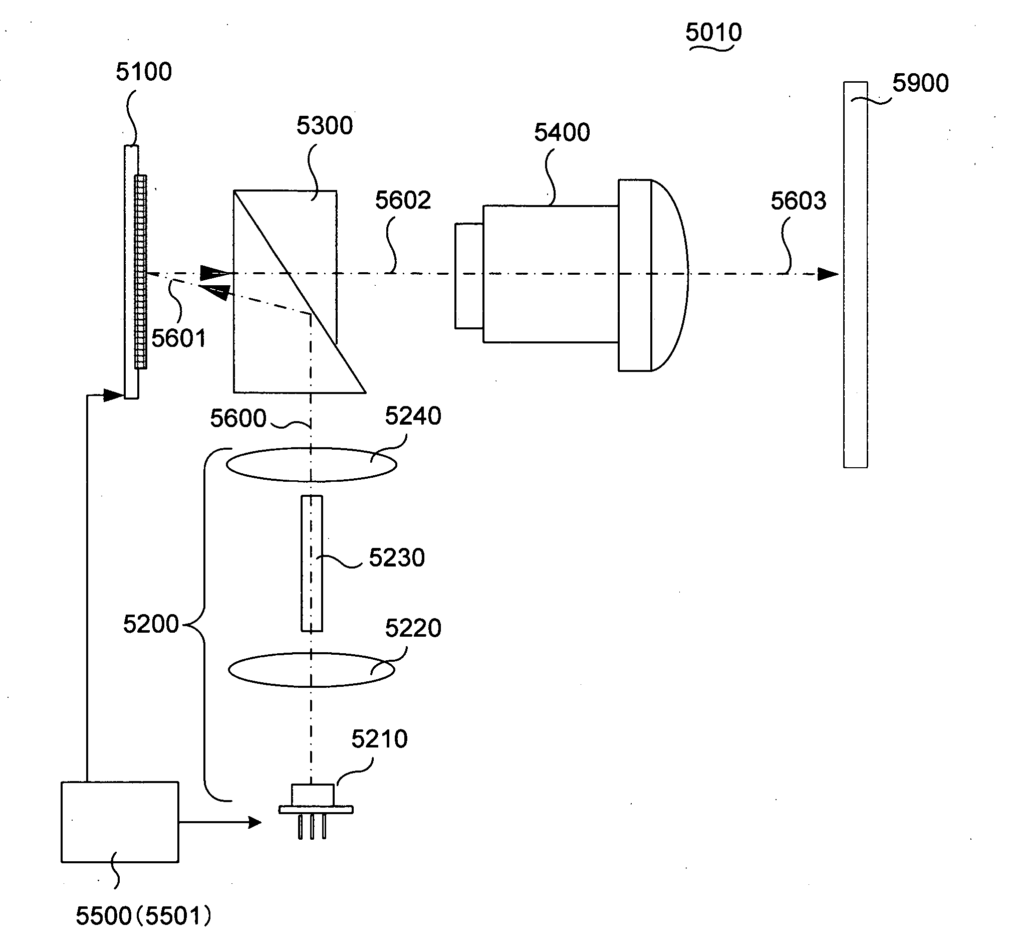
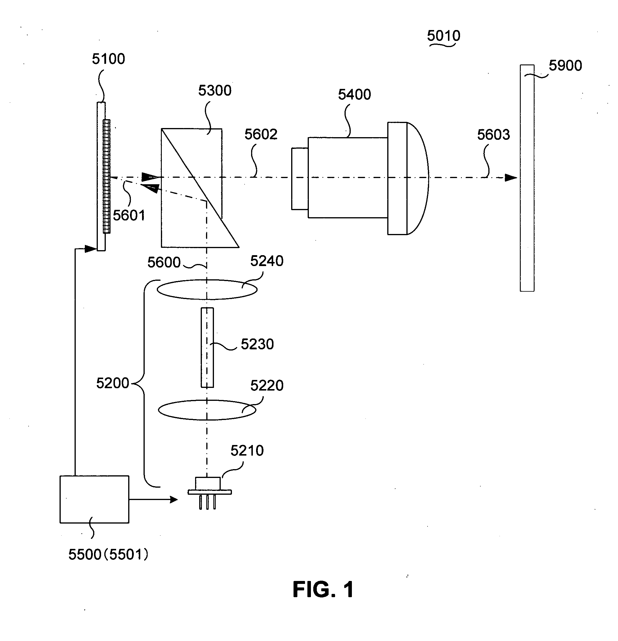
[0092]FIG. 1 is a functional block diagram for showing the configuration of a single-panel projection apparatus according to a preferred embodiment of the present invention. FIG. 1 shows a projection apparatus 5010 that includes a single spatial light modulator (SLM) 5100, a control unit 5500, a Total Internal Reflection (TIR) prism 5300, a projection optical system 5400 and a light source optical system 5200. The projection apparatus 5010 is commonly known as single-panel projection apparatus 5010 because the apparatus is implemented with a single spatial light modulator 5100.

[0093]The projection optical system 5400 is implemented with the spatial light modulator 5100 and TIR prism 5300 along the optical axis of the projection optical system 5400. The light source optical system 5200 is placed with a configuration to have an optical axis matches the optical axis of the projection optical system 5400.

[0094]The TIR prism 5300 directs the illumination light 5600, projected from the li...

embodiment 2

[0136]This embodiment of the present invention uses the control unit 5500 described in FIG. 3A. The light source control unit 5560 of the control unit 5500 generates a control signal to drive the light sources of the respective colors R, G and B on the basis of a light source profile control signal 5801 inputted from the sequencer 5540, while the light source drive circuit 5570 causes the light sources of the respective colors R, G and B to perform pulse emission.

[0137]FIG. 11 is a timing diagram for showing a control for projecting a color display by means of a color sequential control using the control unit 5500, which is shown in FIG. 3A, and on a single-panel projection apparatus comprising one spatial light modulator 5100, as shown in FIG. 1. The display period of one frame (i.e., frame 6700-1) is further divided, in a time series, to the subfields 6701, 6702 and 6703 corresponding to the respective colors R, G and B. Then, the pulse emission of the green laser light source 521...

embodiment 3

[0139]The following is a detail description of another preferred embodiment of the present invention with reference to the accompanying drawings.

[0140]The following description provides various embodiments, with the configurations and operations of the projection apparatuses described in FIGS. 1 through 10 taken into consideration. Note that the same component and signal labels are assigned to the same constituent component or signal comprised in the above-described configurations, and an overlapping description is not provided here.

[0141]The SLM controller 5530 according to the present embodiment is configured to carry out an ON / OFF control of the mirror 5112 using non-binary data 7705 obtained by converting binary data 7704, as exemplified in FIG. 12. Specifically, FIG. 12 exemplifies the case of converting binary data 7704, such as a binary data of 8-bit “10101010”, into non-binary data 7705 that is a bit string having an equal weighting for each digit. A control is carried out t...


PUM


Abstract

The present invention provides a display apparatus, comprising: an a light source for emitting illumination light for transmitting along illumination light path; a display device includes a plurality of pixels for modulating the illumination light for reflecting the illumination light along a projection light path after said illumination light is modulated by said display device; light path change actuator for changing the projection light paths; and a control circuit for controlling the light source, wherein the control circuit controls the light source in response to changes of the projection light path.

Description

CROSS REFERENCE TO RELATED APPLICATIONS[0001]This application is a Non-provisional Application claiming a Priority date of Oct. 2, 2007 based on a previously filed Provisional Application 60 / 997,516 and a Non-provisional patent application Ser. No. 11 / 121,543 filed on May 3, 2005 issued into U.S. Pat. No. 7,268,932. The application Ser. No. 11 / 121,543 is a Continuation In Part (CIP) Application of three previously filed Applications. These three Applications are 10 / 698,620 filed on Nov. 1, 2003, 10 / 699,140 filed on Nov. 1, 2003 now issued into U.S. Pat. No. 6,862,127, and 10 / 699,143 filed on Nov. 1, 2003 now issued into U.S. Pat. No. 6,903,860 by the Applicant of this Patent Applications. The disclosures made in these Patent Applications are hereby incorporated by reference in this Patent Application.BACKGROUND OF THE INVENTION[0002]1. Field of the Invention[0003]The present invention relates to the system configuration and method for controlling an image projection apparatus. More ...

Claims


Application Information

Patent Timeline
Patent Type & Authority Applications(United States)
IPC IPC(8): H04N5/74G03B21/20
CPCG02B27/141G03B33/06G03B33/12H04N5/7458H04N7/012H04N9/3129H04N9/3155H04N2005/745G03B21/2053
Inventor MAEDA, YOSHIHIRONISHINO, HIROKAZUSHIRAI, AKIRAISHII, FUSAO
Owner IGNITE INC
Why Eureka
Try Eureka