Method for Increasing Signal Intensity in An Optical Waveguide Sensor

Inactive Publication Date: 2009-02-05
BAYER TECH SERVICES GMBH
View PDF5 Cites 8 Cited by
  • Summary
  • Abstract
  • Description
  • Claims
  • Application Information

AI Technical Summary

Benefits of technology

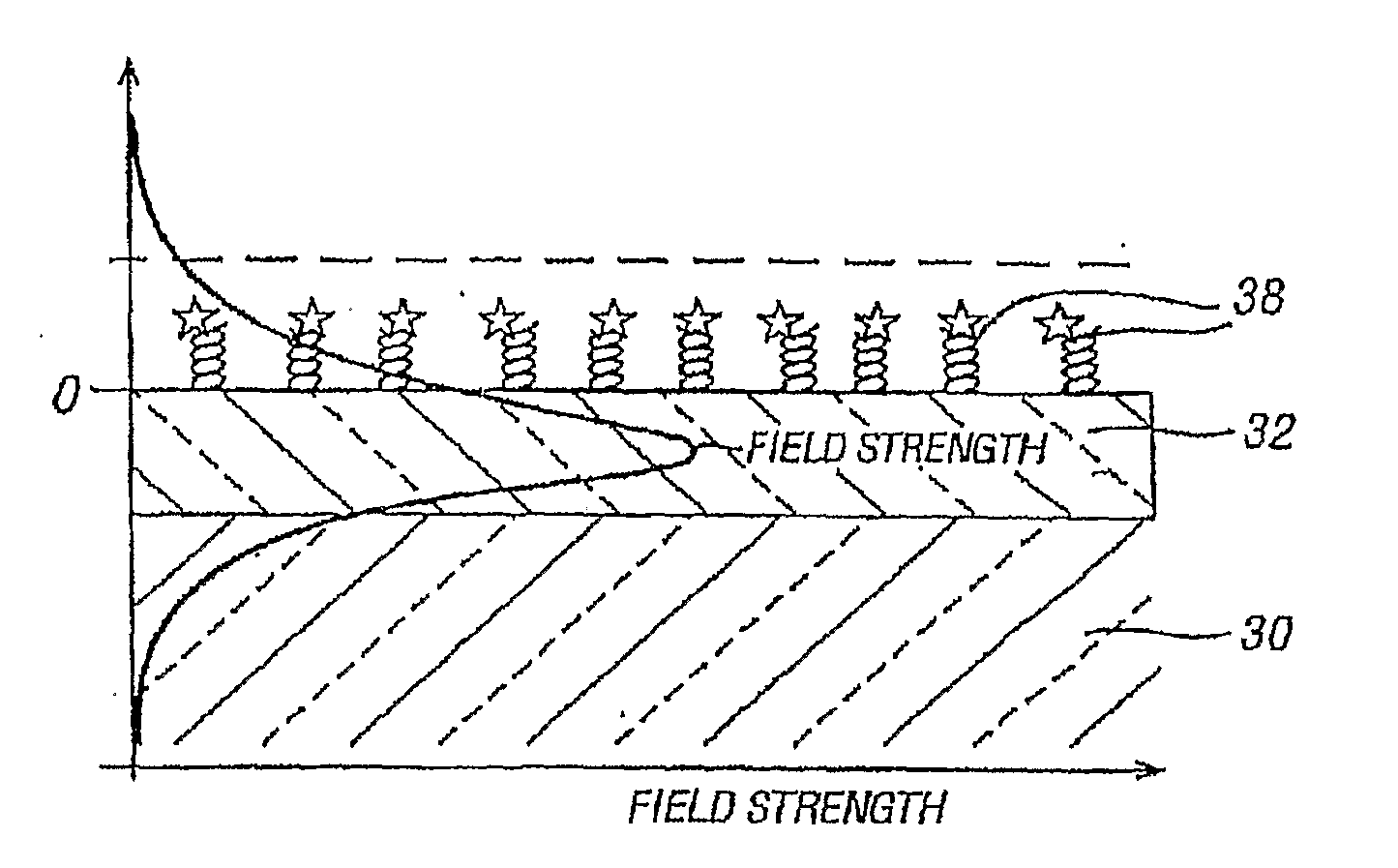
[0005]The present invention relates to novel optical waveguide sensor devices and methods of using optical waveguide sensor devices having improved sensitivity. In particular, the methods and devices of the invention increase the depth of penetration o

Problems solved by technology

Notwithstanding these advantages, the evanescent wave of a waveguide sensor decreases expo

Method used


Image

  • Method for Increasing Signal Intensity in An Optical Waveguide Sensor
  • Method for Increasing Signal Intensity in An Optical Waveguide Sensor
  • Method for Increasing Signal Intensity in An Optical Waveguide Sensor

Examples


examples

[0153]Samples of DNA fragments were labeled with Alexa Fluor 750 dye (AF750, Molecular Probes). The DNA fragments were suspended in a buffer solution with a refractive index of 1.33. The buffer solution was brought in contact with a planar waveguide. The DNA fragments were allowed to hybridize to detection spots on the planar waveguide. Detection spots included capture probes with complimentary chains of DNA fragments. Following hybridization, the buffer solution was replaced with index matching liquids (immersion fluids) from Cargille Labs, Cedar Grove, N.J. 07009 (www.cargille.com) with various indices of refraction. The observed intensity data is displayed in FIG. 8 as a function of refractive index (x axis with intensity on the y axis). The graph reflects that an observed maximum improvement exists arising from the selection of an immersion fluid.

[0154]Fluorescence observed from a planar waveguide using a buffer solution with DNA was compared with observations made when the buff...


PUM


Abstract

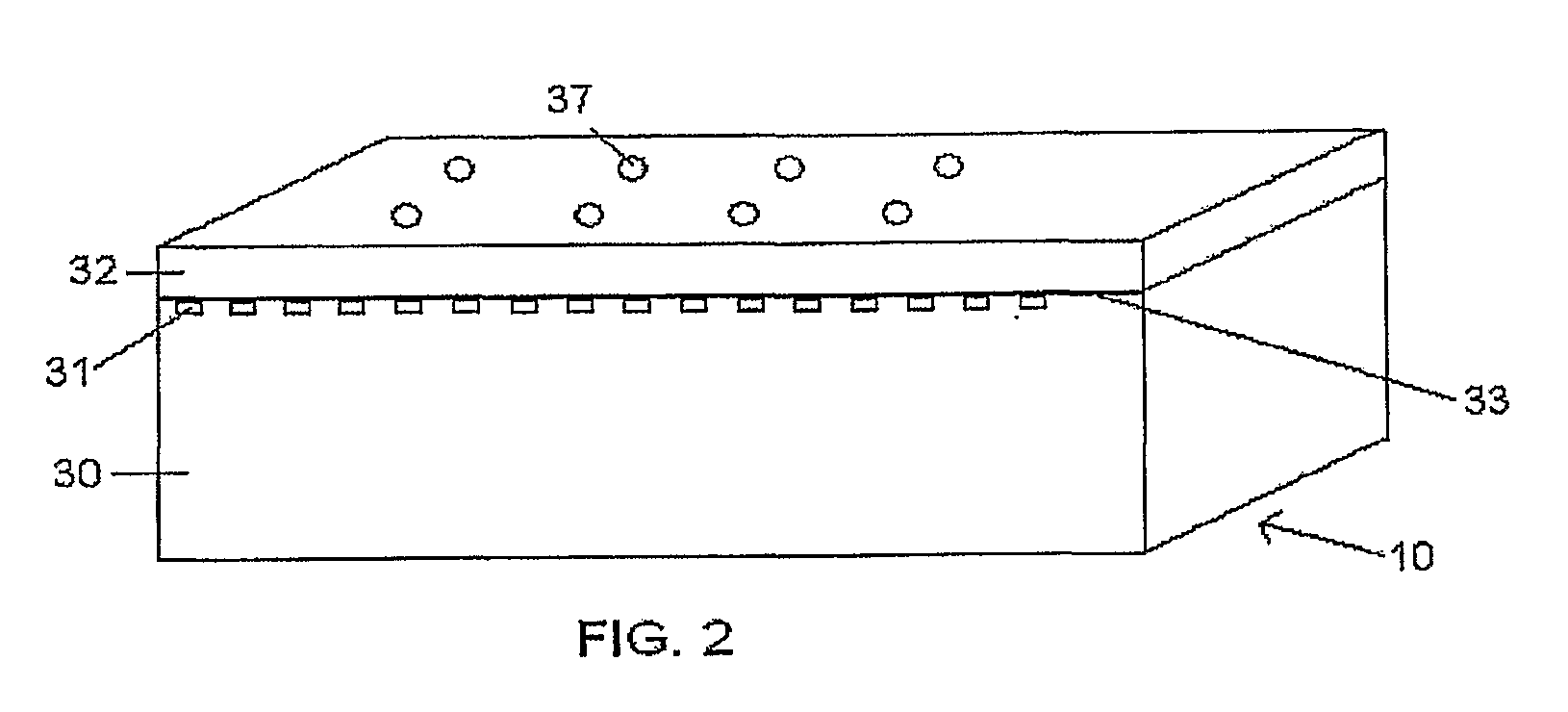
A sensor platform for use in sample analysis comprises a substrate (30) of refractive index m and a thin, optically transparent layer (32) of refractive index (n2) on the substrate, where n2 is greater than n1. The platform includes one of more sensing areas each for one or more capture elements. The platform also includes an immersion fluid with a refractive index n3 greater than an aqueous buffer but less than n2 to enhance the fluorescent signal of an affinity reaction. Also disclosed are an apparatus incorporating the platform and a method of using the platform.

Description

TECHNICAL FIELD OF THE INVENTION[0001]This invention relates generally to the field of optical waveguide sensors and methods of detecting analytes using optical wave guide sensors.BACKGROUND OF THE INVENTION[0002]A variety of optical techniques are used to analyze biological samples based on measured changes in absorption, fluorescence, scatter, and refractive index. For example, optical wave guide sensors utilize optical waveguide element that respond to a change in environment, such as binding of a target analyte to its surface. The optical waveguiding element conveys light from one point to another through an optically transparent elongated structure by modal transmission, total internal reflection, or total reflectorization, while substantially confining the radiation to a region within and adjacent to its surfaces. An optical waveguide sensor typically includes an optically transparent substrate, an optically transparent film bound to a surface of the substrate, and an analyte ...

Claims


Application Information

Patent Timeline
IPC IPC(8): G02B6/00
CPCB82Y15/00B82Y30/00G01N21/774G01N21/648G01N21/6428
Inventor IZMAILOV, ALEXANDRE
Owner BAYER TECH SERVICES GMBH
Why Eureka
Try Eureka