Hydrogen gas sensor

Inactive Publication Date: 2009-02-05
FIDELITY NATIONAL INFORMATION SERVICES
View PDF2 Cites 23 Cited by
  • Summary
  • Abstract
  • Description
  • Claims
  • Application Information

AI Technical Summary

Benefits of technology

[0012]The present invention has been contrived in order to solve the problems above, and an object of the present invention is to provide a catalytic combustion type hydrogen gas sensor of a simple structure, which is capable of inhibiting the degradation of the sensitivity thereof over a long period of time even in the presence of a silicon compound being a catalyst poison.

Problems solved by technology

However, it is known that when vapor of a silicon compound being a catalyst poison is present in the atmosphere where the gas sensor is used, the catalyst becomes poisoned, leading to a change in the characteristics of the gas sensor.
Therefore, the problem in the hydrogen gas sensor for a fuel cell is that the sensitivity of the hydrogen gas sensor is reduced due to the silicon compound.
Particularly because a catalytic combustion type gas sensor combusts gas by means of a catalyst and detects the gas, it is known that the catalytic activity is reduced by a small amount of silicon compound as well, leading to a significant decrease in the sensitivity of the gas sensor.
However, due to a large ventilation resistance of this filter configured by the activated carbon, the amount of a target detection gas flowing into the gas sensor is reduced, causing the degradation of detection sensitivity.
Also, the net or other member is required to hold the activated carbon, which leads to a cost increase.
Moreover, there are management problems of requiring management of the amount of activated carbon held on the net or the like and requiring management of the net or the like for holding the activated carbon.
In addition, there is a quality problem that the fine granular activated carbon that fell off the net or the like adheres to the detection element 21.
This idea, however, makes the structure of the gas sensor complicated, and there is a large amount of gas that flows into the gas sensor without coming into contact with the inner wall or baffles of the introducing passage; which makes it impossible to expect sufficient removal of the silicon compound.

Method used


Image

  • Hydrogen gas sensor
  • Hydrogen gas sensor
  • Hydrogen gas sensor

Examples


first embodiment

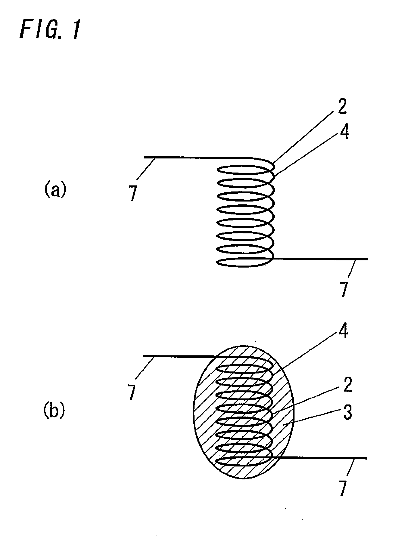
[0048]The first embodiment according to the present invention is described with reference to FIG. 1.

[0049]A detection element 1 of this hydrogen gas sensor has a sensing part 2 and a silicon trapping body 3.

[0050]The sensing part 2 has a function of being heated by Joule heat generated by energization of the sensing part 2, a function of combusting hydrogen gas while being heated, and a function of outputting a change in electrical resistance of the sensing part 2 indicative of hydrogen gas concentration, the change in electrical resistance being caused by an increase in temperature of the sensing part 2 caused by the combustion heat of the hydrogen gas.

[0051]In the present embodiment, the sensing part 2 is configured by a heating resistor 4 only. Therefore, the heating resistor 4 of the present embodiment has the function of being heated by Joule heat generated by the energization, and the function of outputting a change in electrical resistance of the sensing part 2 indicative of ...

second embodiment

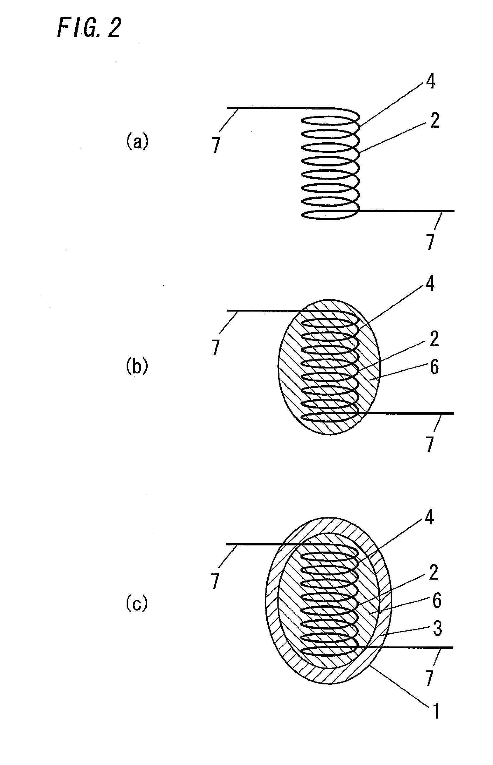
[0103]A second embodiment according to the present invention is described with reference to FIG. 2.

[0104]A detection element 1 of this hydrogen gas sensor has a sensing part 2, a heat insulating body 6 and a silicon trapping body 3.

[0105]The sensing part 2 with the same functions and the same structure as that in the first embodiment can be formed by the same method as in the first embodiment, as shown in FIG. 2(a).

[0106]The heat insulating body 6 is formed so as to cover the entire sensing part 2 and to come into contact with the surface of the sensing part 2 as shown in FIG. 2(b). This heat insulating body 6 is interposed between the sensing part 2 and the silicon trapping body 3. The heat insulating body 6 has a function of allowing a gaseous matter that has passed through the silicon trapping body 3 to reach the sensing part 2, and a function of inhibiting the movement of heat between the sensing part 2 and the silicon trapping body 3.

[0107]The heat insulating body 6 can be form...

third embodiment

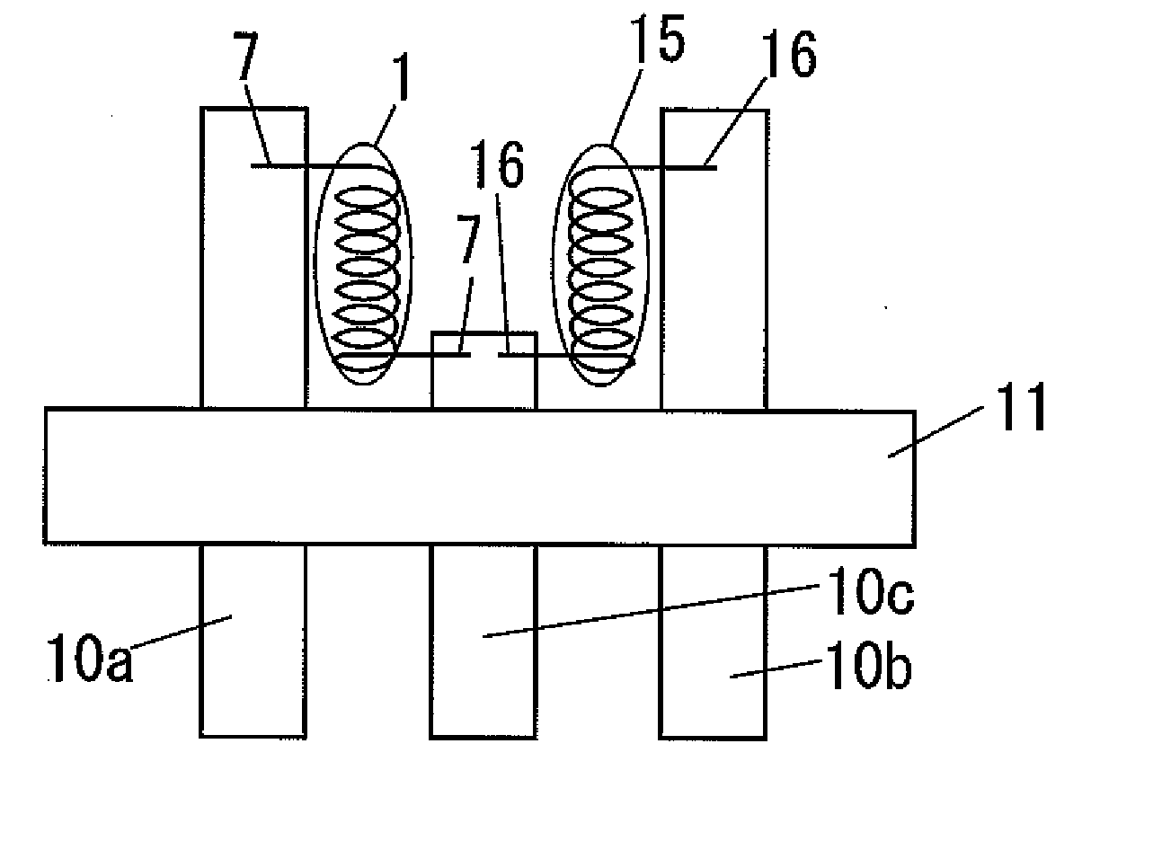
[0122]In each of the above embodiments the hydrogen gas sensor can be provided with a compensation element 15 in addition to the detection element 1. As shown in FIG. 6, in the present embodiment the compensation element 15 is provided in the configurations of the first and second embodiments where the bead-shaped detection element 1 is provided.

[0123]The compensation element 15 has the same structure as the detection element 1 provided in the hydrogen gas sensor, except that the compensation element 15 has a non-sensing part instead of the sensing part 2, the non-sensing part having the same structure as the sensing part 2 except for the function of combusting the hydrogen gas while being heated (specifically, except for a hydrogen combustion catalytic activity).

[0124]Specifically, in the case of the first embodiment or the second embodiment, the heating resistor 4 of each embodiment is subjected to the processing for elimination of the hydrogen combustion catalytic activity. The p...


PUM


Abstract

The present invention provides a catalytic combustion type hydrogen gas sensor of a simple structure, which is capable of inhibiting the degradation of the sensitivity thereof over a long period of time even in the presence of a silicon compound being a catalyst poison. This hydrogen gas sensor is equipped with a detection element 1 having a sensing part 2 and a silicon trapping body 3. The sensing part 2 has a function of being heated by Joule heat generated by energization of the sensing part 2, a function of combusting hydrogen gas while being heated, and a function of outputting a change in electrical resistance of the sensing part 2 indicative of hydrogen gas concentration, the change in electrical resistance being caused by an increase in temperature of the sensing part 2 caused by the combustion heat of the hydrogen gas. The silicon trapping body 3 covering the sensing part 2 contains a silicon-trapping material that functions to trap a silicon compound from a gaseous matter passing through the silicon trapping body 3.

Description

TECHNICAL FIELD[0001]The present invention relates to a catalytic combustion type hydrogen gas sensor which is used for detecting hydrogen gas.PRIOR ART[0002]A semiconductor type or catalytic combustion type gas sensor is widely known as a conventional hydrogen gas sensor for detecting the hydrogen concentration in the atmosphere. Especially the catalytic combustion type gas sensor, a sensor for converting reaction heat generated due to combustion of combustible gas on a sensor surface into an electric signal, is characterized by having a simple structure and linear characteristics of output signals.[0003]FIG. 8 shows a conventional catalytic combustion type gas sensor disclosed in Japanese Patent Application Publication H10-90210. A detection element 21 of this gas sensor is configured by a combustor 22 for combusting combustible gas and a heating resistor 23 for heating the combustor 22 with Joule heat generated in accordance with energization of the combustor 22.[0004]The combust...

Claims


Application Information

Patent Timeline
IPC IPC(8): G01N31/12
CPCG01N27/16
Inventor KODA, HIROSHIIIDA, KAZUYASU
Owner FIDELITY NATIONAL INFORMATION SERVICES
Why Eureka
Try Eureka