High frequency power amplifier and high frequency heating device

a high-frequency power amplifier and heating device technology, applied in amplifiers, amplifiers with semiconductor devices/discharge tubes, amplifiers, etc., can solve the problems of transmission loss inhibiting the reduction of power consumption, the difficulty of reducing the size of the harmonic control circuit composed of microstrip lines, etc., to reduce the transmission loss in the harmonic control circuit and reduce the transmission loss

Inactive Publication Date: 2009-02-12
PANASONIC CORP
View PDF0 Cites 15 Cited by
  • Summary
  • Abstract
  • Description
  • Claims
  • Application Information

AI Technical Summary

Benefits of technology

[0011]Further, even with the use of a printed circuit board with high quality, the open stubs formed of microstrip lines have a low Q value of the resonance, around 100, and therefore, incorporation of the harmonic control circuit causes transmission loss to inhibit reduction in power consumption.
[0041]High frequency heating devices require a high output power of 100 W or higher as an output of a high frequency power amplifier to heat objects. The transmission loss in a harmonic control circuit becomes large in association with the output of the high frequency power amplifier, which means that reduction in transmission loss is demanded in the harmonic control circuit. The high frequency power amplifier in accordance with the present invention uses the dielectric resonators with a high Q value of the resonance in the a harmonic control circuit, thereby remarkably reducing the transmission loss in the harmonic control circuit. Namely, the high frequency power amplifier in accordance with the present invention is useful for the high power application with output power of 100 W or higher, such as in a high frequency heating device and the like.

Problems solved by technology

In practice, however, the dielectric constant of the printed circuit board forming open stubs and the like is so low that it is difficult to reduce the size of the harmonic control circuit composed of the microstrip lines.
Further, even with the use of a printed circuit board with high quality, the open stubs formed of microstrip lines have a low Q value of the resonance, around 100, and therefore, incorporation of the harmonic control circuit causes transmission loss to inhibit reduction in power consumption.

Method used


Image

  • High frequency power amplifier and high frequency heating device
  • High frequency power amplifier and high frequency heating device
  • High frequency power amplifier and high frequency heating device

Examples


embodiment 1

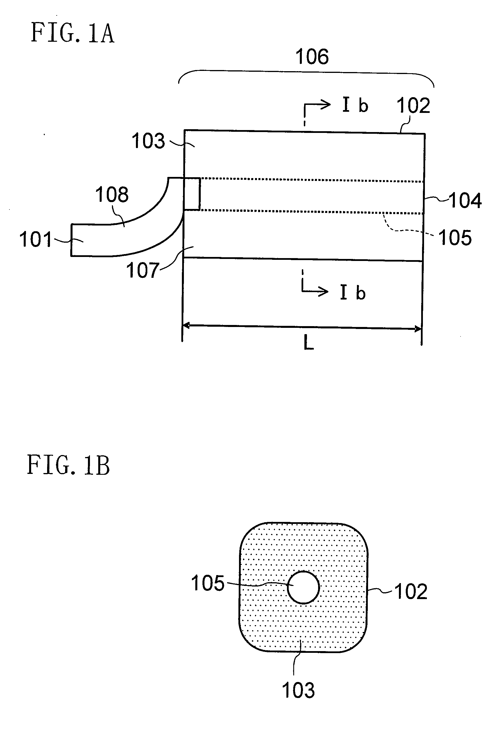
[0054]FIG. 1A and FIG. 1B are a side view and a sectional view, respectively, of a dielectric resonator in accordance with the present invention.

[0055]In a dielectric resonator 106, as shown in FIG. 1A and FIG. 1B, a strip line 105 as a signal line is covered with a dielectric material 103 and the dielectric material 103 is covered with a grounded external conductor 102.

[0056]Accordingly, when an electromagnetic wave is input to the strip line 105, the dielectric resonator 106 confines the input electromagnetic wave, so that the dielectric resonator 106 can have excellent resonance characteristics with a Q value of the resonance of 1000 or more.

[0057]In general, the transmission loss in a harmonic control circuit for controlling the harmonics of an input electromagnetic wave is determined according to the Q value of resonance.

[0058]In the present invention, a harmonic control circuit has dielectric resonators with a high Q value of resonance when compared with stubs on a conventiona...

embodiment 2

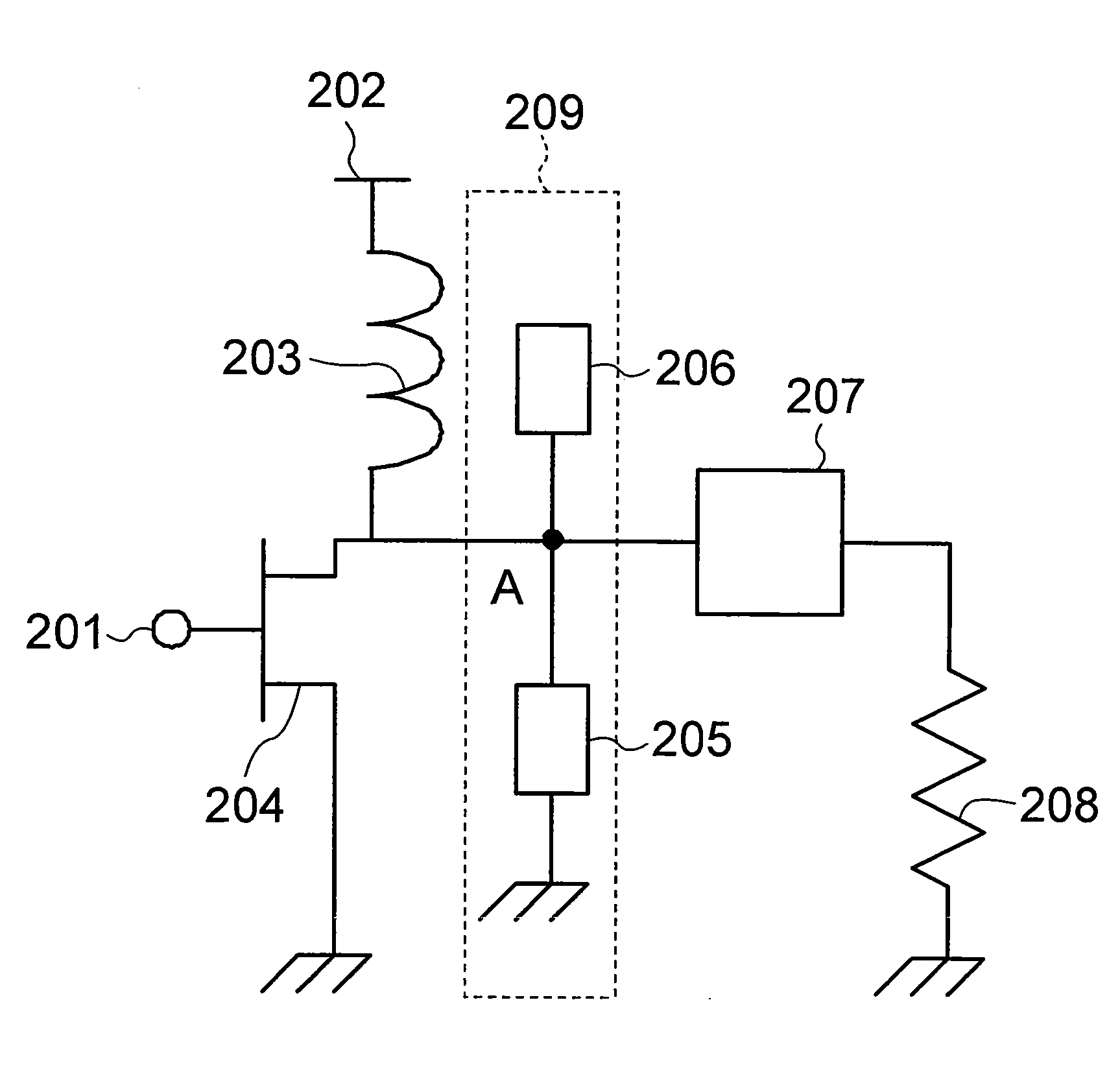
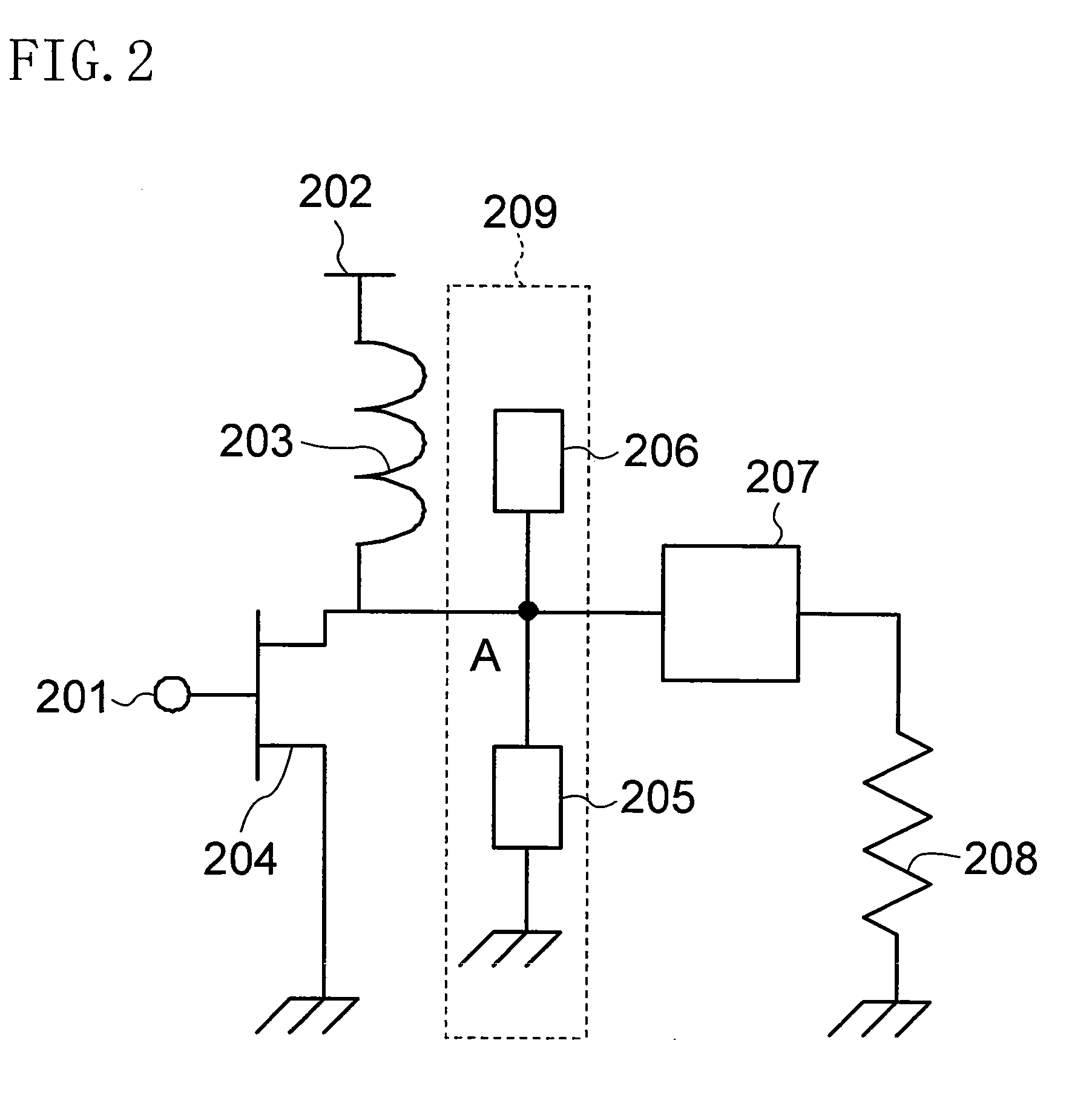
[0066]FIG. 2 is a circuit diagram of a high frequency power amplifier in accordance with Embodiment 2 of the present invention. The high frequency power amplifier of FIG. 2 includes an amplification element 204, such as a transistor or the like, a harmonic control circuit 209, an output matching circuit 207, and a load resistor 208. Reference numeral 201 denotes an input end of a high frequency signal, 202 denotes a DC bias end for driving the amplification element 204, and 203 denotes a choke inductor for cutting a high frequency.

[0067]The high frequency signal input from the input end 201 is amplified in the amplification element 204, passes through the harmonic control circuit 209 and the output matching circuit 207, and is supplied to the load resistor 208.

[0068]The output matching circuit 207 solves impedance mismatch between the output end of the output matching circuit 207 and the load resistor 208 and usually adjusts the impedance on the amplification element side so as to b...

embodiment 3

[0080]FIG. 3 is a circuit diagram of a high frequency power amplifier in accordance with Embodiment 3 of the present invention. The difference from Embodiment 2 of the present invention lies in that the second dielectric resonator 205 is replaced by a third dielectric resonator 301. Herein, the third dielectric resonator 301 is connected at the one end thereof to the output end of the amplification element 204 via the connection end A and is opened at the other end, and the axial length thereof is adjusted so as to correspond to 3λ / 8.

[0081]As described in Embodiment 2 of the present invention, the first dielectric resonator 206 allows the impedances for the second, sixth, tenth, . . . , 2(2m−1)-th harmonics to be short-circuited.

[0082]Further, with the first and third dielectric resonators 206, 301 of which total axial length corresponds to λ / 2, the fundamental wave forms an amplitude loop at the open end of the first dielectric resonator 206 while forming an amplitude loop at the o...


PUM


Abstract

A high frequency power amplifier includes an amplification element, a harmonic control circuit, an output matching circuit, and a load resistor. A high frequency signal input from an input end is amplified in the amplification element, passes through the harmonic control circuit and the output matching circuit, and is then supplied to the load resistor. The harmonic control circuit includes a first dielectric resonator and a second dielectric resonator.

Description

BACKGROUND OF THE INVENTION[0001]1. Field of the Invention[0002]The present invention relates to high frequency power amplifiers and particularly relates to a high frequency power amplifier including a harmonic control circuit connected to an output end of an amplification element and to a microwave heating device for heating a to-be-heated object.[0003]2. Description of Related Art[0004]High frequency power amplifiers are devices for amplifying and outputting an input high frequency signal and are incorporated in high frequency oscillators, high frequency transmitters, and the like. The power consumption of the high frequency power amplifiers is so large that the high frequency power amplifiers consume almost all supplied power necessary for driving the high frequency oscillators and the high frequency transmitters, which obstructs reduction in power consumption.[0005]To tackle this problem, studies for attaining high power efficiency in high frequency power amplifiers have been cu...

Claims


Application Information

Patent Timeline
Patent Type & Authority Applications(United States)
IPC IPC(8): H03F3/60
CPCH03F1/56H03F3/217H03F2200/451H03F2200/387H03F2200/423H03F3/60
Inventor UNO, TAKASHIYAHATA, KAZUHIROSAKAI, HIROYUKI
Owner PANASONIC CORP
Why Eureka
Try Eureka