Method of fabricating hermetic terminal and hermetic terminal, method of fabricating piezoelectric oscillator and piezoelectric oscillator, oscillator, electronic appliance, and radio clock

a technology of which is applied in the field of methods of fabricating hermetic terminals and hermetic terminals, and methods of fabricating piezoelectric oscillators and piezoelectric oscillators, which can solve the problems of reducing stiffness, affecting the reliability of the position of connecting, and unable to maintain the state of being parallel, so as to achieve the effect of improving reliability, ensuring reliability and improving stiffness

Inactive Publication Date: 2009-02-12
SII CRYSTAL TECH
View PDF1 Cites 1 Cited by
  • Summary
  • Abstract
  • Description
  • Claims
  • Application Information

AI Technical Summary

Benefits of technology

[0043]In accordance with the oscillator, the electronic appliance, and the radio clock according to the invention, since they include the small-sized piezoelectric oscillator with its reliability ensured, the oscillator, the electronic appliance, and the radio clock themselves can be reduced in size as well as their reliability can be improved.
[0044]In accordance with the method of fabricating a hermetic terminal according to the invention, and the hermetic terminal according to the invention obtained by the method, since the lead is prevented from being eccentric and the reliability of the position of connecting the piezoelectric vibrating piece is improved, the piezoelectric oscillator using the hermetic terminal can be reduced in size, and the reliability can

Problems solved by technology

However, in the case in which the leads are made narrower than the current form, the stiffness is decreased, and then it is likely to deform the leads in the process of fabrication.
When the outer lead portions become deformed, they cannot maintain themselves in the state of being parallel with each other.
Thus, the quality is degraded, and the oscillator cannot be used as a product.
Consequently, it is likely to cause a reduction in yields.
In addition, in the process of fabrication, the outer lead portions are entangled with the outer lead portions of another hermetic terminal, which might temporarily stop the production line.
Also in this point, it is likely to cause a reduction in yields.
Particularly, the more size reduction is aimed, the more the problems might occur noticeably.
On this account, in the fabricating method under present conditions, it is difficult to fabricate a piezoelectric oscillator of high yields and high quality which can be further reduced in size.
Particularly, it is difficult to fabricate a hermetic terminal configuring a piezoelectric oscillator.
However, the method before still has the following problems.
However

Method used


Image

  • Method of fabricating hermetic terminal and hermetic terminal, method of fabricating piezoelectric oscillator and piezoelectric oscillator, oscillator, electronic appliance, and radio clock
  • Method of fabricating hermetic terminal and hermetic terminal, method of fabricating piezoelectric oscillator and piezoelectric oscillator, oscillator, electronic appliance, and radio clock
  • Method of fabricating hermetic terminal and hermetic terminal, method of fabricating piezoelectric oscillator and piezoelectric oscillator, oscillator, electronic appliance, and radio clock

Examples


first embodiment

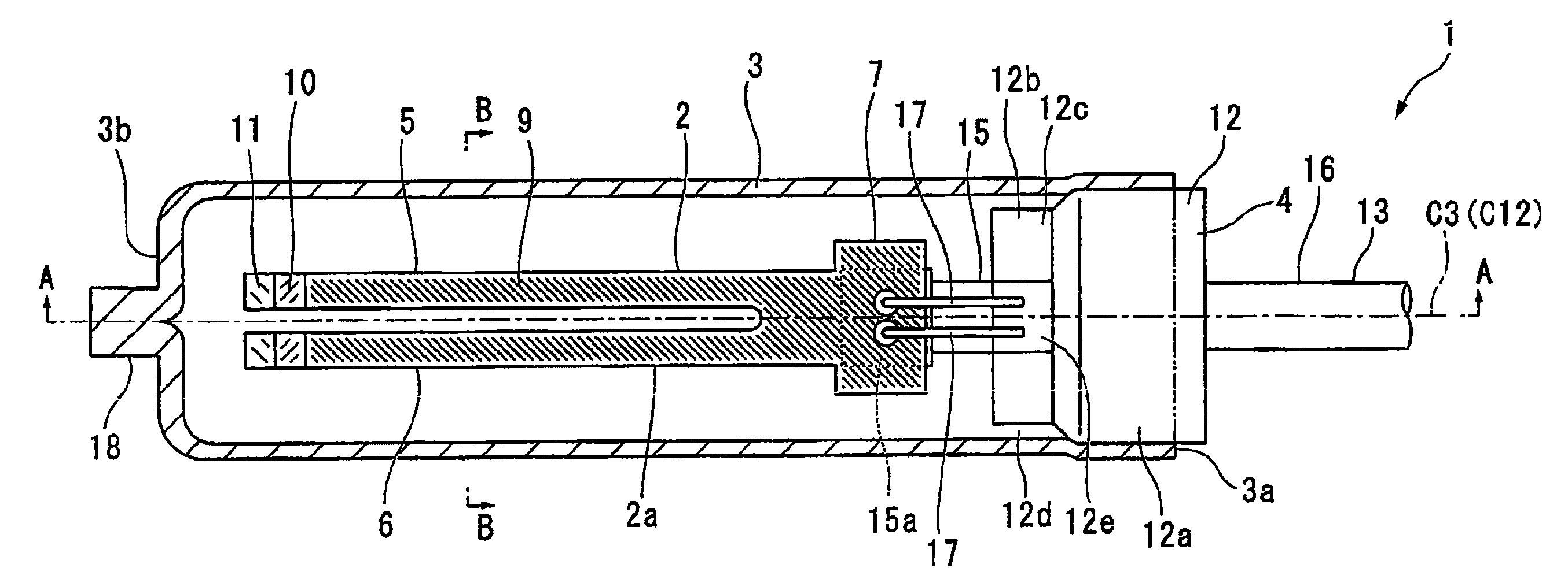
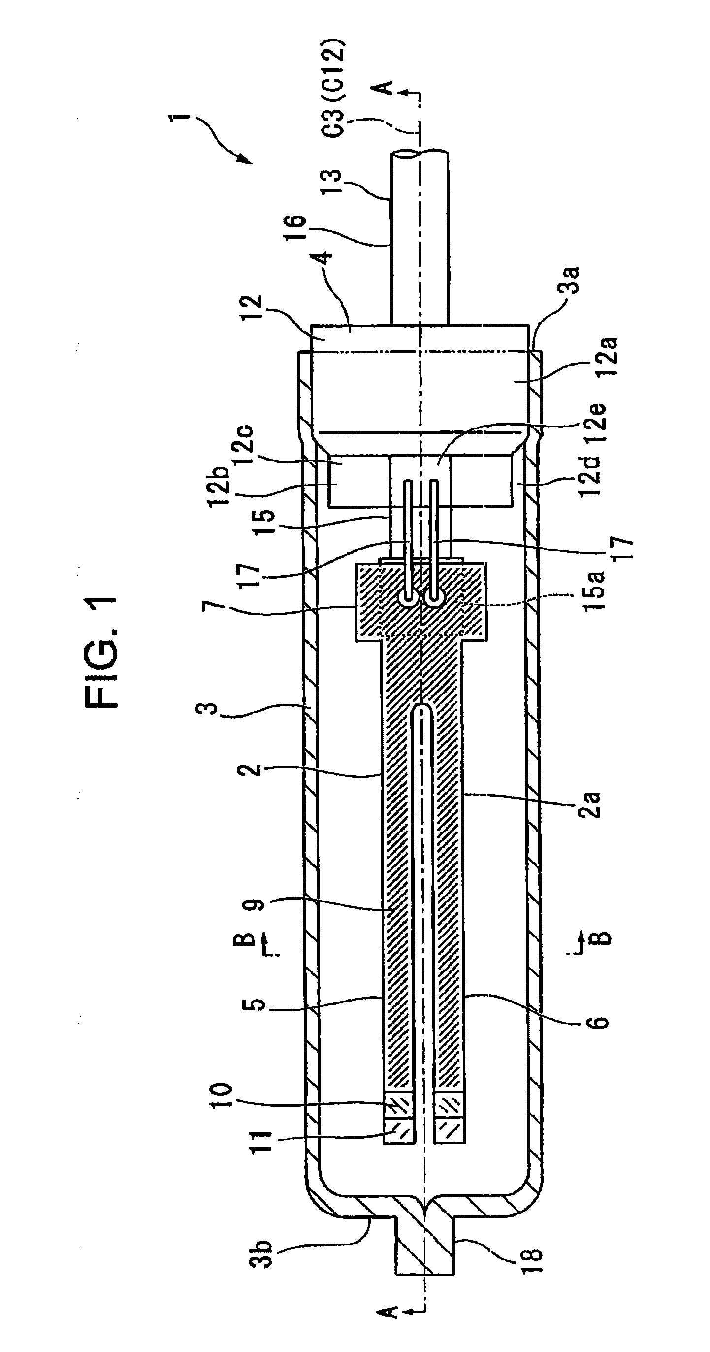
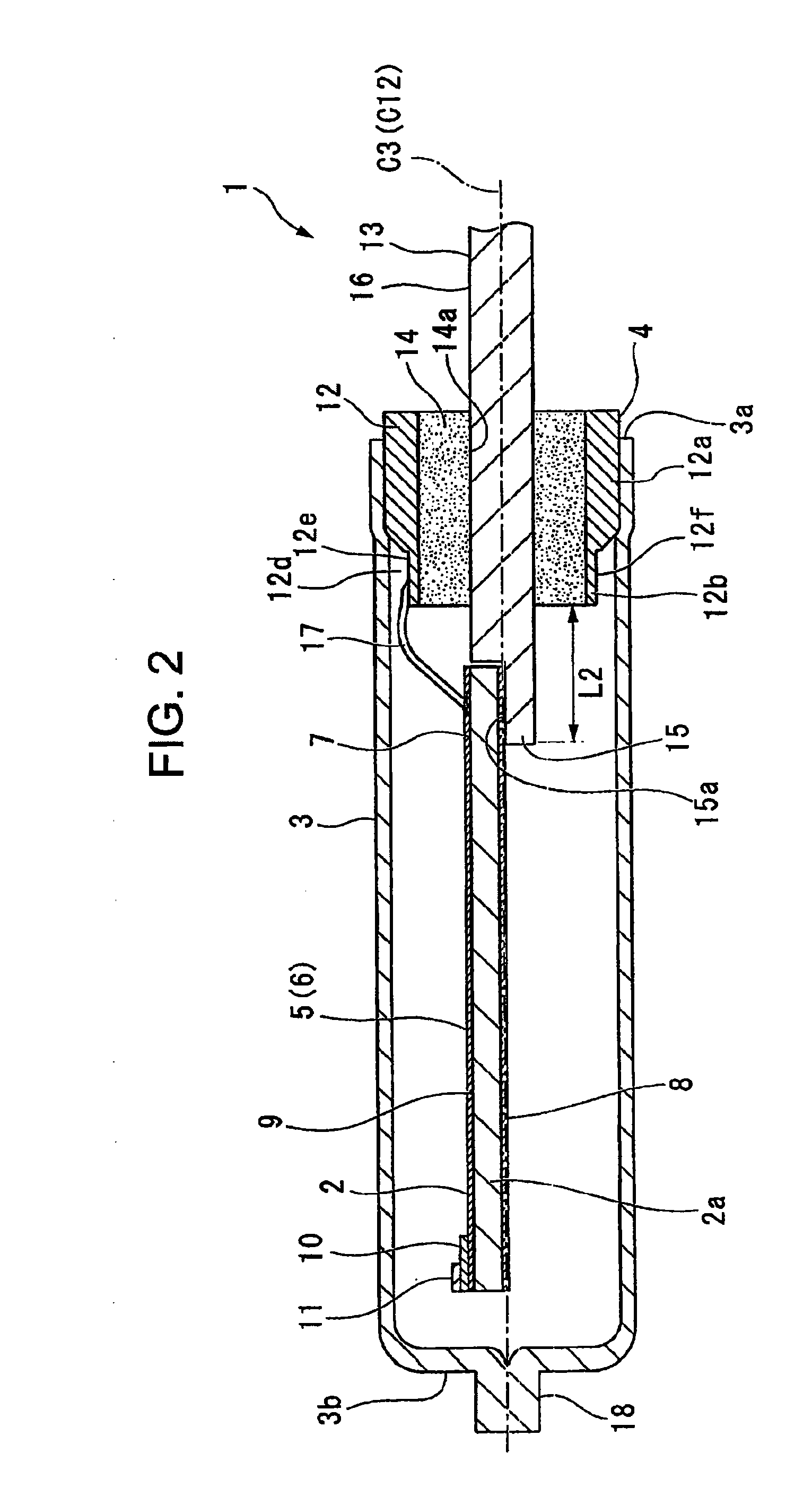
[0077]FIGS. 1 to 3 each show a diagram depicting a piezoelectric oscillator according to a first embodiment of the invention. FIG. 1 shows a cross sectional side view depicting the piezoelectric oscillator according to the embodiment overall, FIG. 2 shows a cross section depicting line A-A shown in FIG. 1, and FIG. 3 shows a cross section depicting line B-B shown in FIG. 1.

[0078]As shown in FIGS. 1 to 3, a piezoelectric oscillator 1 according to the embodiment is a cylinder package piezoelectric oscillator, which is configured to include a piezoelectric vibrating piece 2, a case 3 in a nearly cylindrical shape with a bottom which accommodates the piezoelectric vibrating piece 2 therein and covers therearound, and a hermetic terminal 4 which hermetically seals an opening 3a of the case 3. In the embodiment, the piezoelectric vibrating piece 2 is a tuning fork vibrating piece, which is formed of a quartz crystal piece 2a in a nearly plate shape having a pair of oscillating arm portion...

second embodiment

[0127]FIGS. 25 and 26 each show a second embodiment of the invention. In the embodiment, the members overlapping with the members used in the embodiment described above are designated the same numerals and signs, omitting explanations.

[0128]As shown in FIGS. 25 and 26, this piezoelectric oscillator 50 according to the embodiment is a surface mounted piezoelectric oscillator in which the piezoelectric oscillator 1 according to the first embodiment is resin molded. More specifically, the piezoelectric oscillator 50 includes a case 3, a hermetic terminal 4 which hermetically seals an opening 3a of the case 3, a piezoelectric vibrating piece 2, not shown, arranged inside the case 3, and a resin body 51 which is formed of a resin for covering the case 3, a first outer lead portion 16 and a second outer lead portion 18. To each of the first outer lead portion 16 and the second outer lead portion 18, an external terminal 52 is connected. The external terminal 52 includes a fitting portion ...

third embodiment

[0130]FIG. 27 shows a third embodiment of the invention. In the embodiment, the members overlapping with the members used in the embodiment described above are designated the same numerals and signs, omitting explanations.

[0131]FIG. 27 shows a schematic diagram depicting the configuration of a tuning fork quartz crystal oscillator according to the invention, showing a plan view depicting a surface mounted piezoelectric oscillator using the piezoelectric oscillator discussed above. As shown in FIG. 27, in this oscillator 100 according to the embodiment, a cylinder package piezoelectric oscillator 1 is configured as an oscillating element electrically connected to an integrated circuit 101. In addition, the piezoelectric oscillator 1 is the same as that of the first embodiment, omitting the explanations. The oscillator 100 has a substrate 103 on which an electronic component 102 such as a condenser is mounted. The substrate 103 is mounted with the integrated circuit 101 for the oscill...


PUM

PropertyMeasurementUnit
Electrical conductivityaaaaaaaaaa

Abstract

A method of fabricating a hermetic terminal includes: joining and firing wherein a bar-shaped member to be a lead is inserted into a ring, and they are fired to form a hermetic terminal intermediate having the bar-shaped member fixed in the ring; flattening wherein an end part of the bar-shaped member to be the inner lead portion of the lead is flattened to form a stair portion; and shaping wherein an end part of the stair portion is cut to shape the stair portion into a predetermined shape, wherein in the joining and firing step, a solid round bar longer than the lead is used as the bar-shaped member, and one end side of the bar-shaped member to be the inner lead portion is inserted into the ring so that the one end side is longer than the inner lead portion in the hermetic terminal as a completed product.

Description

RELATED APPLICATIONS[0001]This application claims priority under 35 U.S.C. §119 to Japanese Patent Application No. JP2007-209101 filed on Aug. 10, 2007, the entire content of which is hereby incorporated by reference.BACKGROUND OF THE INVENTION[0002]1. Field of the Invention[0003]The present invention relates to a method of fabricating a hermetic terminal and a hermetic terminal, a method of fabricating a piezoelectric oscillator and a piezoelectric oscillator, an oscillator, an electronic appliance, and a radio clock.[0004]2. Description of the Related Art[0005]In recent years, mobile telephones and portable information terminal devices employ a piezoelectric oscillator using quartz crystal as a time source, a timing source of control signals, and a reference signal source. As this type of piezoelectric oscillator, various ones are offered. As one of them, a cylinder package piezoelectric oscillator formed in a cylindrical shape is known.[0006]As shown in FIG. 30, a piezoelectric o...

Claims


Application Information

Patent Timeline
IPC IPC(8): H03B5/36H01R43/20H01R4/02H01L41/22H01L41/053H01L23/04H03B5/32H03H3/02H03H9/02H03H9/10
CPCH03H9/1021H01L2224/48091Y10T29/42Y10T29/49174Y10T29/49181Y10T29/49176H01L2224/45144H01L2924/00014H01L2924/00
Inventor NUMATA, MASASHIKAWADA, YASUO
Owner SII CRYSTAL TECH
Why Eureka
Try Eureka