
Parking Assist Device and a Method for Electric Power Transmission and Reception Between a Vehicle and a Ground Apparatus

a technology of electric power transmission and ground apparatus, which is applied in the direction of electric devices, gas pressure propulsion mountings, external condition input parameters, etc., can solve the problems of troublesome connection of external chargers by drivers, and achieve the effect of simple charging and less troublesom

Active Publication Date: 2009-02-12
TOYOTA JIDOSHA KK
View PDF8 Cites 68 Cited by
  • Summary
  • Abstract
  • Description
  • Claims
  • Application Information

AI Technical Summary

Benefits of technology

[0006]An object of the invention is to provide a parking assist device allowing simple charging as well as a method for electric power transmission and reception between a vehicle and a ground apparatus.
[0018]According to the invention, the driver can simply performs the charging, and feels less troublesome when performing the charging. These contribute to spread of vehicles requiring the charging.

Problems solved by technology

However, it is troublesome for a driver to connect the external charger to the vehicle via a charge cable every time the driver returns home and parks the vehicle at a parking space.

Method used


Image

  • Parking Assist Device and a Method for Electric Power Transmission and Reception Between a Vehicle and a Ground Apparatus
  • Parking Assist Device and a Method for Electric Power Transmission and Reception Between a Vehicle and a Ground Apparatus
  • Parking Assist Device and a Method for Electric Power Transmission and Reception Between a Vehicle and a Ground Apparatus

Examples


first embodiment

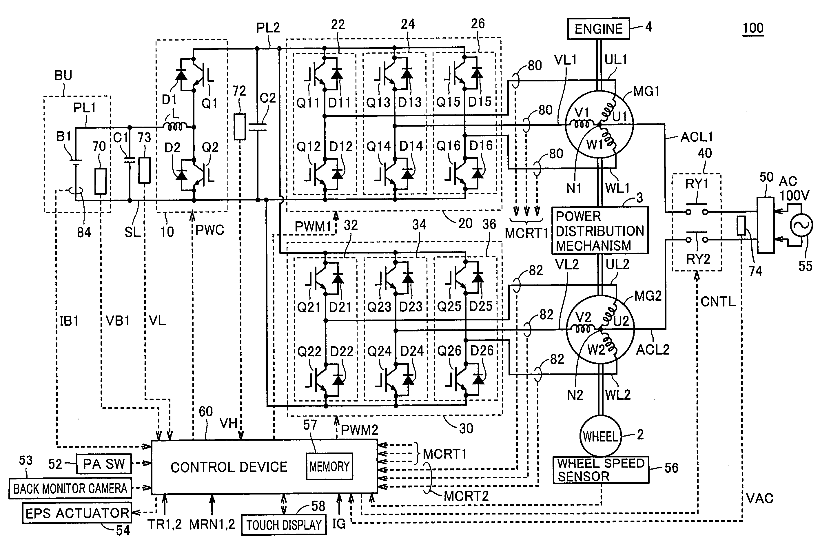
[0033]FIG. 1 is a schematic block diagram of a vehicle 100 according to the invention.

[0034]Referring to FIG. 1, vehicle 100 includes a battery unit BU, a booster converter 10, inverters 20 and 30, power supply lines PL1 and PL2, a ground line SL, U-phase lines ULL and UL2, V-phase lines VL1 and VL2, W-phase lines WL1 and WL2, motor generators MG1 and MG2, an engine 4, a power distribution mechanism 3 and wheels 2.

[0035]Vehicle 100 is a hybrid vehicle employing the motor and the engine for driving the wheels.

[0036]Power distribution mechanism 3 is coupled to engine 4 and motor generators MG1 and MG2 for distributing a power among them. For example, a planetary gear mechanism having three rotation axes of a sun gear, a planetary carrier and a ring gear can be used as the power distribution mechanism. These three rotation axes are connected to engine 4 and motor generators MG1 and MG2, respectively. For example, motor generator MG1 may have a hollow rotor, and a crank shaft of engine ...

second embodiment

[0148]The first embodiment has been described in connection with the example in which the parking assist device and the charge control device are arranged on only the vehicle side, and are not arranged inside the charger. A second embodiment will be described below in connection with an example in which a control device of the charger and a control device on the vehicle side cooperate to assist the parking and to control the charging.

[0149]FIG. 11 illustrates connection of a connection arm in the second embodiment.

[0150]In FIG. 11, a connection arm 203 can extend from a charger 201 to a vehicle 200 in contrast to the structure in FIG. 9. Charger 201 is internally provided with a power supply control device 202 controlling the apparatus on the ground side in FIG. 11 and a vehicle position detecting unit 231 corresponding to, e.g., a magnetic sensor.

[0151]FIG. 12 is a flowchart illustrating a control structure of a program executed on the vehicle-side and the apparatus-side in the sec...


PUM


Abstract

A parking assist device has a touch display (58) including a display unit for displaying a situation around a vehicle and an input unit for entering a target parking position of a vehicle, and also has a control device (60) performing parking assist control by calculating a path according to the target parking position. The control device (60) further performs, under a predetermined condition, assist control for position alignment of a vehicle-side power transmission / reception unit placed on the vehicle with an apparatus-side power transmission / reception unit of an apparatus placed on a ground. Preferably, the parking assist device further has a back monitor camera (53) for taking an image of a surrounding situation of the vehicle. When an identifier indicating the apparatus-side power transmission / reception unit is present in the vicinity of the target parking position in the taken surrounding situation, the control device (60) recognizes the position of the identifier and performs the position alignment assist control.

Description

TECHNICAL FIELD[0001]The invention relates to a method for electric power transmission and reception between a vehicle and a ground apparatus.BACKGROUND ART[0002]In recent years, hybrid vehicles have received great attention as environmentally friendly vehicles. The hybrid vehicle employs, as drive sources, a conventional engine as well as a battery, an inverter and an electric motor driven by the inverter.[0003]Japanese Patent Laying-Open No. 8-154307 has disclosed a hybrid vehicle provided with an external charging function. The hybrid vehicle includes a battery that can be charged by an external charger, an electric motor driving wheels by an electric power supplied from the battery, control means for controlling an operation of the motor, an internal combustion engine directly and indirectly used for driving the wheels and traveling time related quantity calculating means that calculates a quantity related to a traveling time elapsed after the external charger charged the batter...

Claims


Application Information

Patent Timeline
IPC IPC(8): B60Q1/48B60K6/28B60L50/16B60R16/04B60R21/00B60W10/26B60W30/00B62D6/00B62D101/00B62D113/00B62D119/00
CPCB60L11/123Y02T90/163B60L11/1812B60L11/1814B60L11/1816B60L11/1825B60L15/007B60L2220/14B60L2220/54B60L2230/16B60R1/00B60R2300/305B60R2300/806B60W2420/403B60W2550/20B60W2550/402B62D15/0285Y02T10/6217Y02T10/641Y02T10/7005Y02T10/7077Y02T10/7088Y02T90/121Y02T90/127Y02T90/128Y02T90/14B60L11/14B60L53/14B60L53/22B60L50/61B60L50/16B60L53/24B60L53/31B60L53/305B60W2554/00B60W2556/50Y02T10/62Y02T10/64Y02T10/7072Y02T90/12Y02T90/16Y02T10/70B60R1/26B60K6/28B60W10/26B60W20/00B60R16/04
Inventor OYOBE, HICHIROSAINAKAMURA, MAKOTO
Owner TOYOTA JIDOSHA KK
Learn More