Device for Processing Material by Mixing and/or Plasticization or Agglomeration

Active Publication Date: 2009-02-12
SCHULZ KATHARINA
13 Cites 7 Cited by

AI-Extracted Technical Summary

Problems solved by technology

Achieving a high degree of mixing is important for this purpose and the twin-screw extruders known up to this point have not been entirely satisfactory in this regard.
This has the result that to achieve a sufficient throughput, large quantities of material to be processed must be received in the intake area of the screws.
By selecting a suitable geometry of the screw channels, this prob...

Method used

[0022]The motor 3 drives the drive shaft 9, on which multiple chain wheels 10 are seated, which are connected via drive chains 11 to further chain wheels 12, which are seated on a further drive shaft 13. The two shafts 9, 13 are mounted so they are rotatable in a shared housing 14 and are driven to revolve in the same direction via the drive chains 11. Their axes are parallel to one another. The axis 15 of the shaft 9 is coincident with the axis of the screw 2. The shaft 9 is connected rotationally fixed via an extension 17 to the core of the screw 2. The shaft 9 having its extension 17 may be implemented in one piece with the core of the screw 2. However, if such an implementation would be too long, a coupling 18 may be provided between the extension 17 and the core of the screw 2. Not only is the production of the screw 2 made easier in this manner, but rather also its disassembly, for example, for the purpose of replacement or maintenance. The other shaft 13 is connected via an apparatus 19 to the screw 1, this apparatus 19 providing the screw 1 with a periodic acceleration and/or deceleration of the peripheral velocity as the drive shaft 13 rotates. For this purpose, the apparatus 19 has two Cardan joints 20, 21 which are connected to one another rotationally fixed. One Cardan joint 20 is connected rotationally fixed to the shaft 13, the other Cardan joint 21 to a connection shaft 22, which may be implemented in one piece with the core of the screw 1 or is connected rotationally fixed to the core of the screw 1 via a coupling 25. The two Cardan joints 20, 21 form a universal shaft 26 together with a linkage 23 connecting them. The linkage 23 may be formed in the simplest case by a rod whose axis is identified by 24. Because the axes 4, 5 of the two screws 1, 2 are not parallel to one another, but the axes 15, 16 of the two drive shafts 9, 13 are, the angle α between the axis 16 of the shaft 13 and the axis 24 of the linkage 23 is greater than the angle β which the axis 24 of the linkage 23 encloses with the axis 4 of the screw 1. The difference of the two angles α,β forms an angle of inflection, which has the result that the universal shaft 26 having the two Cardan joints 23, 24 causes the cited acceleration and deceleration of the rotational movement of the screw 1. The screw 2, in contrast, is driven at constant peripheral velocity.
[0026]The embodiment of FIG. 7 shows a twin-screw extruder whose construction is similar to that of FIG. 1, a difference only exists in that the two screws 1, 2 rotating in the same direction are not implemented as conical, but rather cylindrical, so that the two screw axes 4, 5 run parallel to one another. The two drive shafts 9, 13 are also parallel to one another, which results in a very simple design. The two angles α, β are therefore equal to one another. To also achieve the cited desired periodic deceleration and acceleration of the rotational movement of the screw 1 in such a design, the output-side Cardan joint 21 is pivoted by a suitable amount in relation to the drive-side Cardan joint 20 around the axis 24 connecting the two Cardan joints. This relative pivoting of the two Cardan joints 20, 21 may be ach...

Benefits of technology

[0007]The invention is based on the object of solving the problems described in another way and improving the processing of a broad spectrum of types of materials, so that the product obtained at the output of the device meets the requirements, which have increased ever further in recent time. This applies both for achieving an improved degree of mixing in c...

Abstract

Device for processing material by mixing and/or plasticization or agglomeration A device for processing material by mixing and/or plasticization or agglomeration has a screw housing (6), in which at least two screws (1, 2) are situated adjacent to one another. The screw channels (7) are engaged with one another. The screws are driven to rotate by at least one motor (3). The screws (1, 2) are supplied with the material through an intake opening (39) of the screw housing (6) and the processed material leaves the screw housing through at least one outlet opening (51). An apparatus (19) is provided, which in operation of the device provides the gap (8) which exists between adjacent screw channels (7) of the screws (1, 2) alternately with a periodic enlargement or reduction, which is superimposed on the rotational movements of the two screws (1, 2).
In the method for material processing, the material, in addition to the compaction which is caused by the conveyance action of the screws, is subjected to periodic squeezing by the screws.

Application Domain

Transportation and packagingRotary stirring mixers +14

Technology Topic

EngineeringMechanical engineering

Image

  • Device for Processing Material by Mixing and/or Plasticization or Agglomeration
  • Device for Processing Material by Mixing and/or Plasticization or Agglomeration
  • Device for Processing Material by Mixing and/or Plasticization or Agglomeration

Examples

  • Experimental program(1)

Example

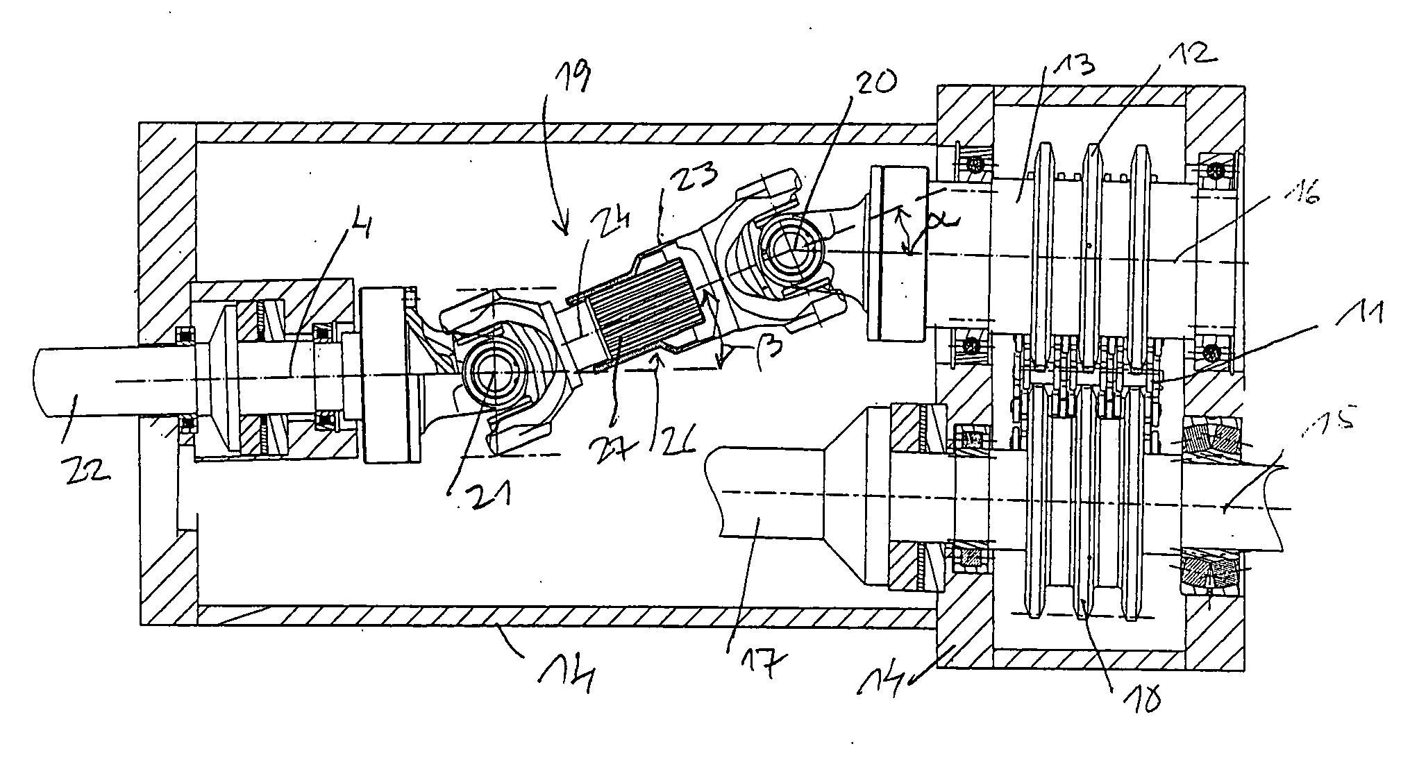
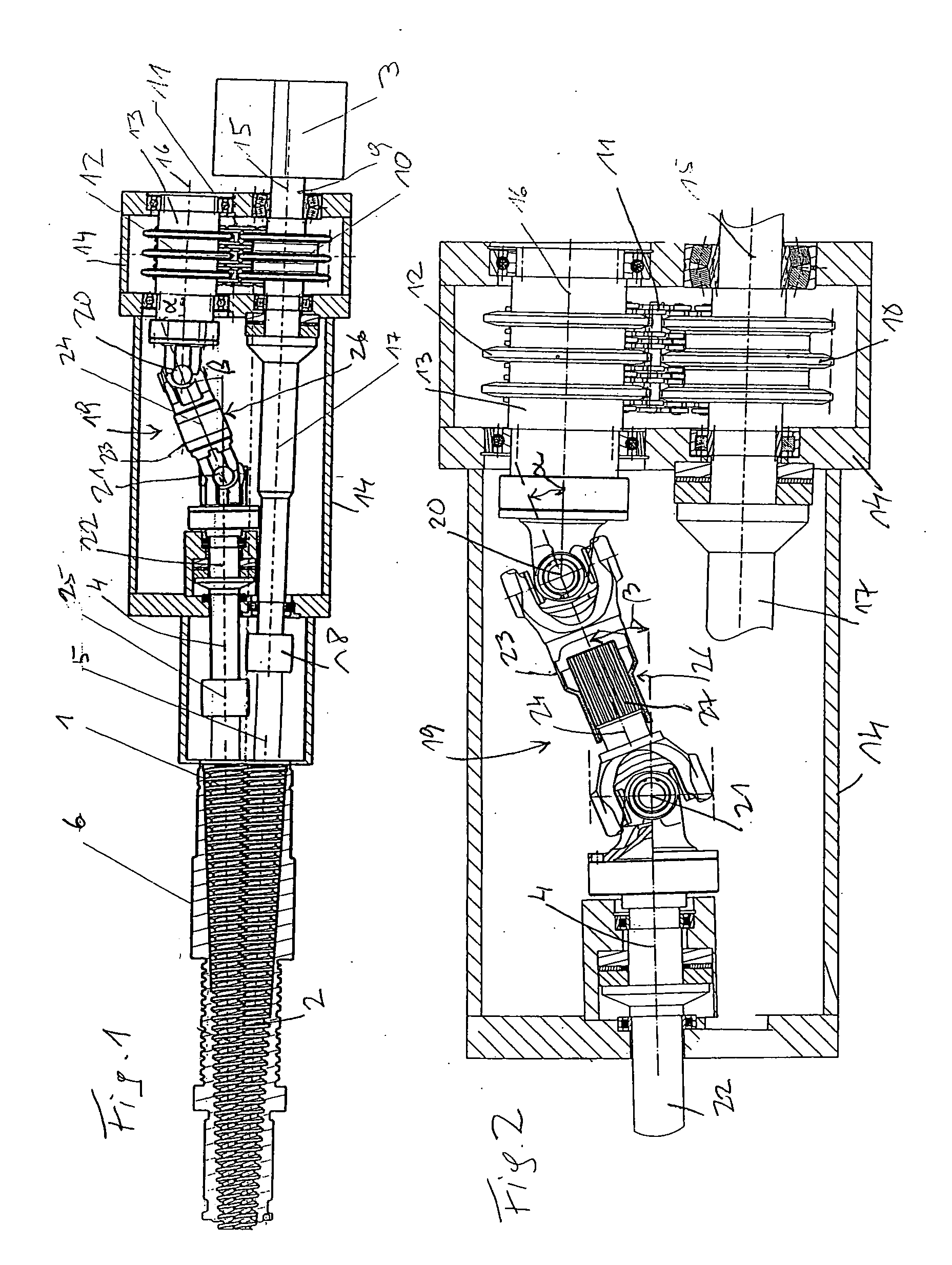
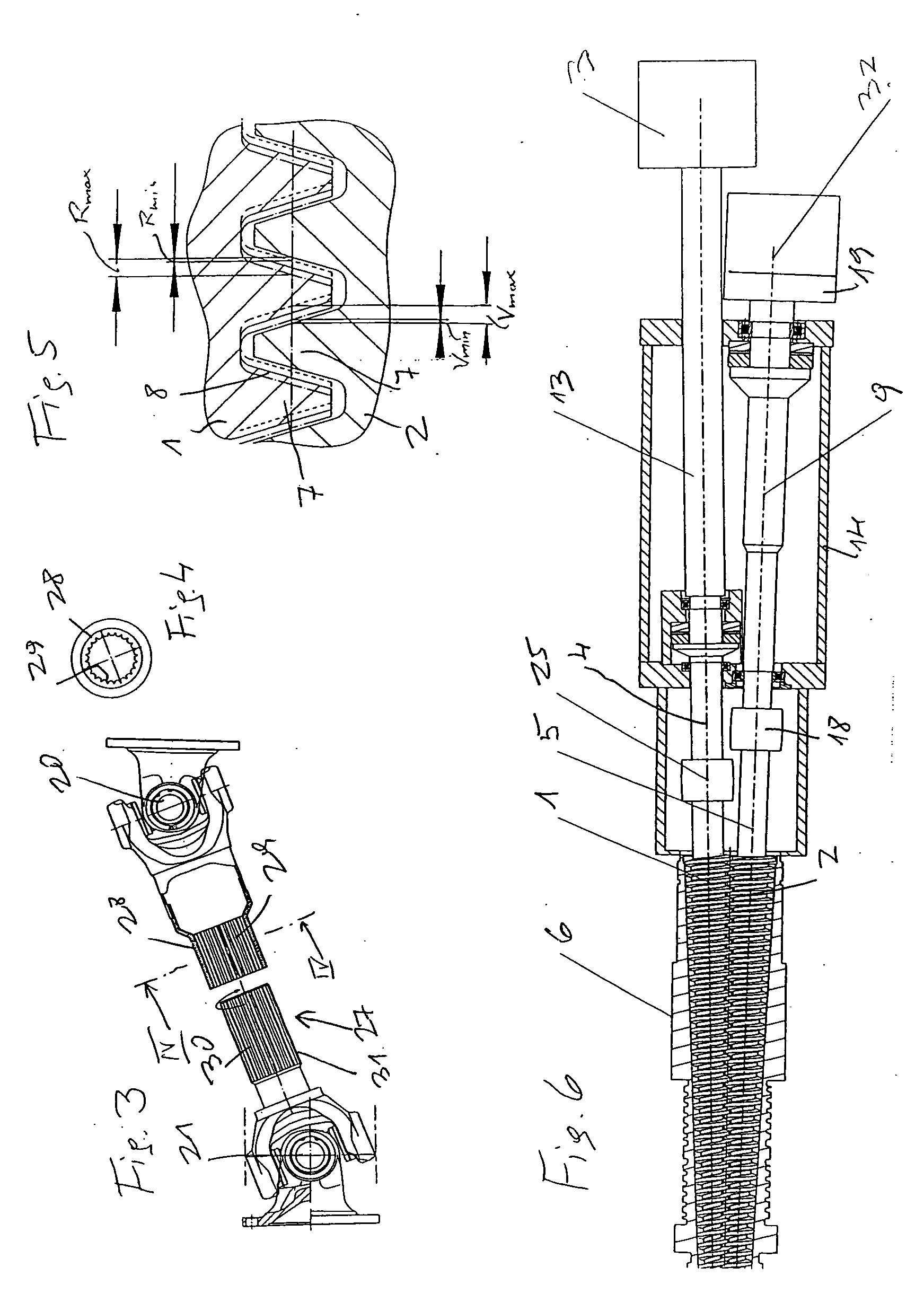
[0021]The exemplary embodiment according to FIGS. 1 through 5 shows a twin-screw extruder having two conical screws 1, 2, which are driven by a shared motor 3 to rotate in the same direction around their axes 4, 5. The conicity of the screws 1, 2 causes their axes 4, 5 to enclose an acute angle with one another. The two screws 1, 2 are mounted in a shared screw housing 6 and their screw channels 7 (FIG. 5) engage in one another, i.e., the screw channels mesh with one another, but are at an axial distance to one another, so that a gap 8 (FIG. 5) remains between the screw channels 7 of the two screws 1, 2.
[0022]The motor 3 drives the drive shaft 9, on which multiple chain wheels 10 are seated, which are connected via drive chains 11 to further chain wheels 12, which are seated on a further drive shaft 13. The two shafts 9, 13 are mounted so they are rotatable in a shared housing 14 and are driven to revolve in the same direction via the drive chains 11. Their axes are parallel to one another. The axis 15 of the shaft 9 is coincident with the axis of the screw 2. The shaft 9 is connected rotationally fixed via an extension 17 to the core of the screw 2. The shaft 9 having its extension 17 may be implemented in one piece with the core of the screw 2. However, if such an implementation would be too long, a coupling 18 may be provided between the extension 17 and the core of the screw 2. Not only is the production of the screw 2 made easier in this manner, but rather also its disassembly, for example, for the purpose of replacement or maintenance. The other shaft 13 is connected via an apparatus 19 to the screw 1, this apparatus 19 providing the screw 1 with a periodic acceleration and/or deceleration of the peripheral velocity as the drive shaft 13 rotates. For this purpose, the apparatus 19 has two Cardan joints 20, 21 which are connected to one another rotationally fixed. One Cardan joint 20 is connected rotationally fixed to the shaft 13, the other Cardan joint 21 to a connection shaft 22, which may be implemented in one piece with the core of the screw 1 or is connected rotationally fixed to the core of the screw 1 via a coupling 25. The two Cardan joints 20, 21 form a universal shaft 26 together with a linkage 23 connecting them. The linkage 23 may be formed in the simplest case by a rod whose axis is identified by 24. Because the axes 4, 5 of the two screws 1, 2 are not parallel to one another, but the axes 15, 16 of the two drive shafts 9, 13 are, the angle α between the axis 16 of the shaft 13 and the axis 24 of the linkage 23 is greater than the angle β which the axis 24 of the linkage 23 encloses with the axis 4 of the screw 1. The difference of the two angles α,β forms an angle of inflection, which has the result that the universal shaft 26 having the two Cardan joints 23, 24 causes the cited acceleration and deceleration of the rotational movement of the screw 1. The screw 2, in contrast, is driven at constant peripheral velocity.
[0023]FIG. 2 shows this drive of the connection shaft 22 in a larger scale. As shown, the drive side of the Cardan joint 20 is connected rotationally fixed to the drive shaft 13 driven by the motor 3. The other Cardan joint 21 is connected rotationally fixed on its output side to the connection shaft 22, which is in turn connected rotationally fixed to the core of the screw 1, possibly via the coupling 25. The output side of the Cardan joint 20 is connected rotationally fixed in the way typical for universal shafts to the drive side of the Cardan joint 21. However, the angle of this connection is adjustable, so that the cited deceleration or acceleration of the rotation of the screw 1 is variable. For this purpose, the linkage 23 connecting the two Cardan joints 20, 21 rotationally fixed has a coupling 27, using which the rotational position of the output-side Cardan joint 21 is adjustably changeable in relation to the drive-side Cardan joint 20, around the axis 24 connecting the two Cardan joints 20, 21. This coupling 27 is shown in the disassembled state in FIG. 3. It has a receptacle 28 connected rotationally fixed to the output side of the Cardan joint 20, which is provided with internal teeth 29. Teeth 30, which are positioned on the circumference of a socket pin 31 connected rotationally fixed to the drive side of the Cardan joint 21, may be plugged fitting into these internal teeth 29.
[0024]The enlargement and reduction of the gap 8 caused by the cited periodically changing peripheral velocity of the screw 1 is shown in greater detail in FIG. 5, this gap existing between the screw channels 7 of the two screws 1, 2. A maximum gap width Vmax and a minimum gap width Vmin result for the screw channel 7 of the screw 1 on its forward side, seen in the conveyance direction of the screws, in operation. Similarly, a maximum gap width Rmax and a minimum gap width Rmin result on the rear side of the screw channel 7 of the screw 1. This minimum gap width may be set so small that a contact of screw channels 7 of the two screws 1, 2 opposite to one another is still just avoided. In practice, however, one typically manages with a 40 to 60% change of the screw gap, in relation to the maximum possible dimension of the gap 8. It is typically not necessary to change the profile of the screw channels 7 in relation to typical profile shapes. In special cases, however, adapting the profile of the screw channels 7 appropriately because of the cited reduction and increase of the gap 8 may be indicated.
[0025]The embodiment of FIG. 6 also shows a twin-screw extruder, whose screws 1, 2 rotating in the same direction are implemented as conical, so that the screw axes 4, 5 do not lie parallel to one another. In this embodiment, the cited deceleration and acceleration of the rotational movement of one of the screws (in relation to the constant rotational movement of the other screw) is not achieved by a universal shaft, but rather separate motors 3, 32 are provided for the two screws 1, 2. The motor 3 drives the screw 1 at constant peripheral velocity (which may be adjustably selectable, however), the motor 32, in contrast, is provided with the cited apparatus 19, which provides the screw 2 driven thereby with a periodic acceleration and deceleration superimposed on the constant speed. The size of this acceleration and deceleration is expediently adjustably changeable. Suitable electronic controllers are available for this purpose.
[0026]The embodiment of FIG. 7 shows a twin-screw extruder whose construction is similar to that of FIG. 1, a difference only exists in that the two screws 1, 2 rotating in the same direction are not implemented as conical, but rather cylindrical, so that the two screw axes 4, 5 run parallel to one another. The two drive shafts 9, 13 are also parallel to one another, which results in a very simple design. The two angles α, β are therefore equal to one another. To also achieve the cited desired periodic deceleration and acceleration of the rotational movement of the screw 1 in such a design, the output-side Cardan joint 21 is pivoted by a suitable amount in relation to the drive-side Cardan joint 20 around the axis 24 connecting the two Cardan joints. This relative pivoting of the two Cardan joints 20, 21 may be achieved easily by a coupling according to FIGS. 3, 4. As noted therein, the cited relative pivoting of the two Cardan joints 20, 21 may be adjustably selectable, so that one may adapt to various conditions of the material to be processed.
[0027]The embodiment from FIG. 8 forms a combination of the embodiments from FIGS. 6 and 7. The two screws 1, 2 rotating in the same direction are cylindrical, as in FIG. 7, however, the apparatus 19 which provides the rotational movement of the screw 2 with a periodic deceleration and acceleration in relation to the rotational movement of the screw 1 is implemented as in the embodiment from FIG. 6. As shown in FIG. 8, a change of the type of the cited periodic rotational movement change of the screw 1 may additionally be achieved by a coupling 27 for this purpose.
[0028]A further possibility for the variation of the periodic change of the axial width of the gap 8 is to make the position of the axial direction of the output shaft 22 adjustably changeable in relation to the position of the axial direction of the drive shaft 13.
[0029]The configuration of separate motors 3, 32 for the drive of the two screws 1, 2 makes it possible to make the drive shaft 13 adjustable in the housing 14 in regard to its direction without problems, e.g., by a suitable pivot mount.
[0030]A further possible design for achieving the periodic change of the width of the gap 8 between opposite screw channels 7 of the two screws 1, 2 is to provide one of the two screws with a periodic back-and-forth movement in the direction of its axis, this movement being superimposed on the rotational movement of the screw. An additional drive is necessary for this screw for this purpose. This additional drive may be implemented in such a manner that a fixed curve path is provided, on which a tappet connected to the affected screw runs as the screw rotates. It is expedient to implement such a tappet as a rotor to avoid friction losses. Another possible design comprises forming the cited additional drive by a piston-cylinder assembly, which causes the periodic back-and-forth movement of the screw. Of course, the rotational drive of the affected screw must be implemented appropriately in both cases to permit the cited back-and-forth movement.
[0031]Of course, it is also possible to implement all described designs in such a manner that the two screws 1, 2 rotate in opposite directions. A simple possible design for this purpose is to couple the two drive shafts 9, 13 of the two screws 1, 2 to one another via gear wheels. Which of the two types of drive (opposite or identical directions) is selected for the screws 1, 2 is a function of the existing conditions, conical screws running in the same direction are typically most favorable.
[0032]Although the pitch of the screw channels of the two screws 1, 2 is shown as constant in FIGS. 7 and 8, it is also possible, of course, to implement this pitch as varying over the screw length in such a manner that the desired compaction of the material results in the conveyance direction of the screws 1, 2.
[0033]The filling of twin-screw extruders, as were described above, is shown in FIGS. 9 through 11. The twin-screw extruder 38 (FIGS. 9, 10) provided with the device according to the invention has an intake opening 39 of the screw housing 6 situated in the area of one front end of the screws 1, 2. A funnel 40 is connected to this intake opening 38, against whose top side a horizontally mounted dosing screw 41 presses, which is driven by a motor 42 via a gear 42 in such a manner that material supplied from above via a supply funnel 44 to the dosing screw 38 is always supplied in the desired quantity to the screws 1, 2, so that both overfilling and also idling of the screws are avoided. The material to be processed is frequently thermoplastic material which is to be reprocessed for recycling purposes. This material is frequently formed by PET milled product, which is formed by crushed bottles and must be melted under vacuum, so that oxidation and degradation of the material are avoided as much as possible. If such vacuum handling is desired, the supply of the material shown in FIGS. 9 and 10 must occur under a vacuum seal, a design suitable for this purpose is shown in FIG. 11. For this purpose, a vacuum hose 45 is connected to the funnel 40, which may be terminated on the top and bottom by sliders 46, 47 closing vacuum tight in a way known per se, so that its inner chamber 48 may be evacuated via an evacuation line 49. The dosing screw 41 is not shown in FIG. 11 for the sake of simplicity.
[0034]Another frequently existing application is the compounding of plastics of different types, e.g., polyethylene of lower and higher densities, or polypropylene with polyethylene. The cited periodic change of the width of the gap 8 between opposing screw channels 7 favors the achievement of a desired high degree of mixing. Such a high degree of mixing also results during the processing of pasty and/or powdered materials, of whatever type, e.g., ceramic or mineral materials, such as clay, etc.
[0035]At least one degassing opening 50 may be provided in the housing 6 of the screws 1, 2, to which a suction line (not shown) may be connected, via which gas may be suctioned out of the inner chamber of the screw housing 6.
[0036]The material mixed and/or plasticized and/or agglomerated by the screws 1, 2 is discharged out of the screw housing 6 through at least one outlet opening 51 at the front end of the screw housing 6 facing away from the intake opening 39. An extruder head or a suitable molding facility may be connected to this outlet opening 51.
[0037]In certain applications, it may be advantageous to permit a leakage flow in the two screws 1, 2. Suitable measures for this purpose are known, e.g., flattening at least some screw channels 7 and/or incorporating grooves on at least some flanks of the screw channels 7.

PUM

PropertyMeasurementUnit
Fraction0.4 ~ 0.6fraction
Fraction0.5fraction
Flow rate

Description & Claims & Application Information

We can also present the details of the Description, Claims and Application information to help users get a comprehensive understanding of the technical details of the patent, such as background art, summary of invention, brief description of drawings, description of embodiments, and other original content. On the other hand, users can also determine the specific scope of protection of the technology through the list of claims; as well as understand the changes in the life cycle of the technology with the presentation of the patent timeline. Login to view more.

Similar technology patents

Lipid compositions

ActiveUS20160228462A1improve processing
Owner:AKER BIOMARINE ANTARCTIC

Classification and recommendation of technical efficacy words

  • improve processing

Rotor selection interface and method

ActiveUS20050120142A1improve processing
Owner:THERMO FISHER SCI ASHEVILLE

Multi-scale short read assembly

InactiveUS20100063742A1improve processingefficiently assemble
Owner:HELICOS BIOSCIENCES CORPORATION

Reinforced elastomer preparation, elastomer composite and tire having component thereof

InactiveUS6172138B1reduction of mix energyimprove processing
Owner:THE GOODYEAR TIRE & RUBBER CO

Method of examining a plurality of sites for a clinical trial

InactiveUS20050182663A1improve processingimprove cost effectiveness
Owner:SIEMENS AG

Process of removing calcium and obtaining sulfate salts from an aqueous sugar solution

InactiveUS20090056707A1improve processingimprove downstream processing
Owner:IOGEN ENERGY CORP
Why Eureka
Try Eureka