Method and Apparatus for Radiance Processing by Demultiplexing in the Frequency Domain

a frequency domain and multi-frequency technology, applied in the field of radiance processing by demultiplexing in the frequency domain, can solve the problems of inconvenient use, inconvenient use, and inability to capture a large amount of optical information by conventional cameras

Active Publication Date: 2009-02-12
ADOBE INC
View PDF102 Cites 127 Cited by
  • Summary
  • Abstract
  • Description
  • Claims
  • Application Information

AI Technical Summary

Benefits of technology

[0015]In one embodiment of a frequency domain demultiplexing module, a radiance image may be captured with any of a variety of radiance cameras, including but not limited to various lens-based radiance cameras. The frequency domain demultiplexing module receives an input radiance image and performs a frequency domain demultiplexing method, for example ...

Problems solved by technology

Conventional cameras fail to capture a large amount of optical information.
In particular, a conventional camera does not capture information about the location on the aperture where different light rays enter the camera.
However, this 2-D image contains no information about the directional distribution of the light that strikes the photosensor.
However, frequency domain anal...

Method used


Image

  • Method and Apparatus for Radiance Processing by Demultiplexing in the Frequency Domain
  • Method and Apparatus for Radiance Processing by Demultiplexing in the Frequency Domain
  • Method and Apparatus for Radiance Processing by Demultiplexing in the Frequency Domain

Examples


Embodiment Construction

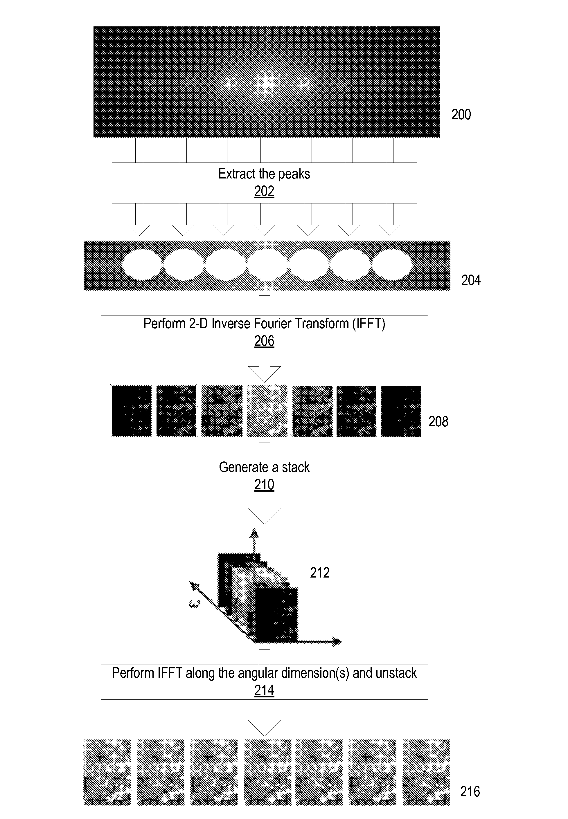
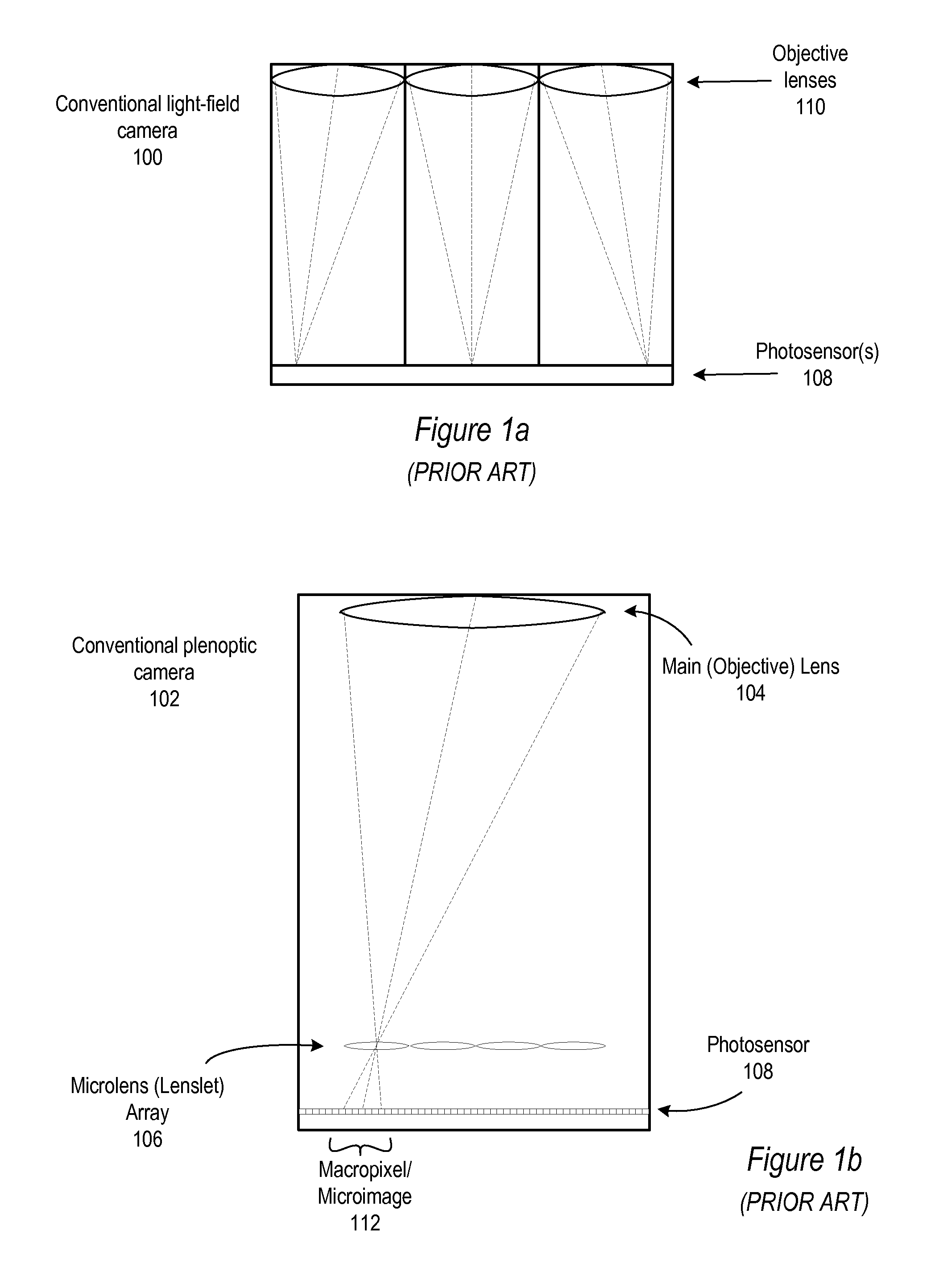
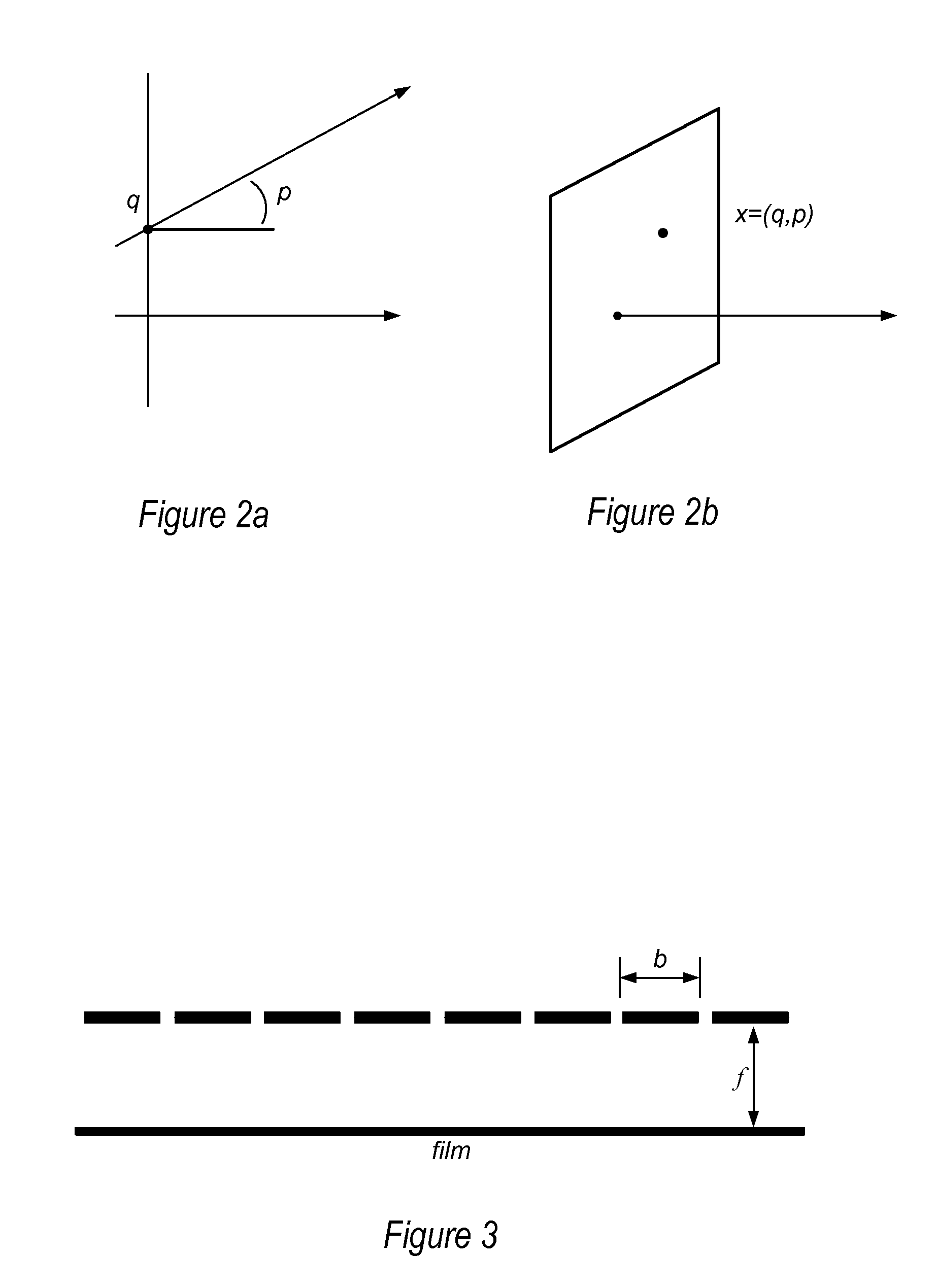
[0050]Various embodiments of a method and apparatus for capturing radiance in the frequency domain, and demultiplexing the captured radiance in the frequency domain, are described. Various embodiments of light-field, or radiance, cameras, including both mask-based and lens-based radiance cameras, are described that multiplex the radiance in the frequency domain by optically mixing different spatial and angular frequency components and capturing the signal via a photosensor (e.g., conventional film or an electronic sensor such as a charge-coupled device (CCD)). Some embodiments of the radiance camera may be based on arrays of “active” optical elements, such as lenses and prisms. Other embodiments of the radiance camera may be based on “passive” optical elements, or masks, such as meshes or grids of circles or pinholes. Both types of radiance cameras may be understood and described according to a mathematical formalism in the frequency domain.

[0051]In the following sections, a mathema...


PUM


Abstract

Method and apparatus for radiance processing by demultiplexing in the frequency domain. A frequency domain demultiplexing module obtains a radiance image captured with a lens-based radiance camera. The image includes optically mixed spatial and angular frequency components of light from a scene. The module performs frequency domain demultiplexing on the radiance image to generate multiple parallax views of the scene. The method may extract multiple slices at different angular frequencies from a Fourier transform of the radiance image, apply a Fourier transform to each of the multiple slices to generate intermediate images, stack the intermediate images to form a 3- or 4-dimensional image, apply an inverse Fourier transform along angular dimension(s) of the 3- or 4-dimensional image, and unstack the transformed 3- or 4-dimensional image to obtain the multiple parallax views. During the method, phase correction may be performed to determine the centers of the intermediate images.

Description

PRIORITY INFORMATION[0001]This application claims benefit of priority of U.S. Provisional Application Ser. No. 60 / 954,238 entitled “Light-Field Capture by Multiplexing in the Frequency Domain” filed Aug. 6, 2007, the content of which is incorporated by reference herein in its entirety.BACKGROUNDDescription of the Related Art[0002]Conventional cameras fail to capture a large amount of optical information. In particular, a conventional camera does not capture information about the location on the aperture where different light rays enter the camera. During operation, a conventional digital camera captures a two-dimensional (2-D) image representing a total amount of light that strikes each point on a photosensor within the camera. However, this 2-D image contains no information about the directional distribution of the light that strikes the photosensor. Directional information at the pixels corresponds to locational information at the aperture.Light-Field or Radiance Photography[0003]...

Claims


Application Information

Patent Timeline
IPC IPC(8): G06K9/36
CPCH04N5/225H04N23/00
Inventor GEORGIEV, TODOR G.INTWALA, CHINTAN
Owner ADOBE INC
Why Eureka
Try Eureka