Filler material, especially for filling cavities, especially of structural elements, method of production and structural element

a filling material and filling technology, applied in the field of filling cavities, can solve the problems of affecting the sintering resistance of such coatings, weak viscosity of such epoxy resin systems, and high cost of rendering such coatings more susceptible to sintering and more reactive at higher temperatures

Inactive Publication Date: 2009-02-12
SIKA TECH AG
View PDF4 Cites 6 Cited by
  • Summary
  • Abstract
  • Description
  • Claims
  • Application Information

AI Technical Summary

Benefits of technology

[0008]It is proposed firstly that the filler material be introduced into cavities in the structural element without requiring expensive structural modifications while obviating the egress of filler material, and secondly that the duroplastic system, for example an epoxy resin system, need not be weakly viscous and relatively highly reactive at the same time.

Problems solved by technology

The notable disadvantage of this method is that a cavity so prepared must be tightly sealed in order to prevent the egress of agglutinant.
The disadvantage attending this method is that the viscosity of such epoxy resin systems must be weak enough to allow application by means of spraying.
It would, however, be more expensive to render such coating more susceptible to sintering and more reactive at higher temperatures.

Method used


Image

  • Filler material, especially for filling cavities, especially of structural elements, method of production and structural element
  • Filler material, especially for filling cavities, especially of structural elements, method of production and structural element

Examples


example 1

Coated Spheres, Viscid Surfaces, Resin System (SikaPower ®9496 / 3).

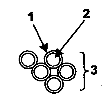
[0024]In this case, hollow steel spheres 3.2 mm in diameter, were used at a packed density of 0.36 g / ml. Employed as the duroplastic 1 for the coating material was a commercially-available structural agglutinant (SikaPower ®0496 / 3). Assuming homogenous coating of the spheres, it was anticipated that the coat enveloping the spheres would have the following thicknesses:

Calculated layer thicknessPercent by weight agglutinantof the coat / agglutinant layer in μm101220303050

[0025]Both spheres and agglutinant (total mass 70 g) were transferred into a beaker and heated to 80° C. Coating took place inside a Speedmixer DAC 150 FV (centrifugal mixer manufactured by Hauschild). This yielded homogenously-coated, slightly viscid, readily transportable spheres. The slightly viscid spheres were then poured into a cylindrical mould that had been treated with a separating agent (substituting for a cavity inside a structural element) and...

example 2

Coated Spheres, Dry Surfaces, Impact-Resistant Modified Epoxy Resin System, Dusted with Butvar

[0027]Duroplastic or agglutinant and process method as in Example 1. The example involving 30% by weight agglutinant (70 g total weight) was repeated. Immediately following coating, the spheres were dusted with 5 g polyvinylbutyral Movital 60 HH. This yielded pourable spheres, which were then transferred into a cylindrical mould, whereby after curing for 30 min. at 180° C., a rigid cylinder was obtained.

example 3

Coated Spheres, Impact-Modified Epoxy Resin System

[0028]A reactive impact-modified epoxy-resin agglutinant was prepared by mixing 100 g of an addition compound comprising bisphenol-A-diglycide ether with dimeric fatty acid (Epoxy Value=2.8 epoxy equivalents / kg) together with 100 g solid epoxy resin (GT 7004, manufactured by Vantico AG, Epoxy Value=1.4 epoxy equivalents / kg) and 50 g of a fluid epoxy resin (GY 250 manufactured by Vantico) at 90° C. inside a planetary mixer.

[0029]Added to the homogenous mixture were 125 g of a reactive polyol (a polyol comprising epoxide groups) 130 g light filler (Extendospheres serving to lower the density of the duroplastic) and 6.5 g pyrogenic silicic acid (Cabosil TS 720, manufactured by Cabot) as well as 12.3 g dicyandiamide.

[0030]The reactive polyol comprising epoxy groups was prepared as follows: 200 g PolyTHF 2000 (PTMEG polytetramethylene ether glycol having a molecular weight of 2000 g / mol OH number 57.5 mg / g KOH) were dessicated inside a va...


PUM

PropertyMeasurementUnit
Thicknessaaaaaaaaaa
Thicknessaaaaaaaaaa
Thicknessaaaaaaaaaa

Abstract

The invention relates to a filler material, especially for filling cavities, especially of structural elements, to a method of production and to a structural element. The inventive filler material comprises particles that are coated with a reactive duroplast, whereby the reactive duroplast is non-viscous at room temperature when not yet reacted.

Description

THE TECHNICAL DOMAIN[0001]The present invention relates to a filler material, especially for filling cavities, in particular of structural elements, whereby said filler material comprises particles that are coated with a reactive duroplastic. The present invention relates furthermore to a process for manufacturing a filler material, in particular a filler material as proposed whose particles are coated with a reactive duroplastic. The present invention relates furthermore to a structural element having a cavity.THE STATE OF THE ART[0002]The production of both vehicles and containers requires that load-bearing metal components be at once light and exhibit considerable rigidity or solidity. This objective can, in many instances, be achieved if metal components are designed to have, for example, a sandwich construction wherein the cavities are filled with a porous material, for example, foam materials. Such sandwich structures are produced by bonding two metal covering layers to a foam...

Claims


Application Information

Patent Timeline
IPC IPC(8): B32B3/26B32B27/38C08K9/08C08L63/00C09C3/10C09J163/00
CPCC08K9/08C08L63/00C09J163/00Y10T428/269Y10T428/2998C08L2666/18Y10T428/249972
Inventor FINTER, JURGENBLANK, NORMAN
Owner SIKA TECH AG
Why Eureka
Try Eureka