Electrode stack and bipolar secondary battery

Inactive Publication Date: 2009-02-12
TOYOTA JIDOSHA KK
View PDF6 Cites 75 Cited by
  • Summary
  • Abstract
  • Description
  • Claims
  • Application Information

AI Technical Summary

Benefits of technology

[0007]In the electrode stack structured in this manner, the shaft member is arranged to pass through the cathode, anode and the electrolyte and, therefore, displacement of the interference between the cathode, anode and electrolyte can effectively be prevented. Thus, increase in interface resistance can be curbed.
[0008]Preferably, the shaft member is a bolt. In the electrode stack structured in this manner, the cathode, anode and electrolyte are fastened by the bolt and, therefore, the effects mentioned above can more effectively be attained.
[0009]Preferably, the shaft member is formed of an insulating material. Preferably, an insulating member is arranged between an inner wall of the hole and the bolt. In the electrode stack structured in this manner, short-circuit between electrodes through the shaft member can be prevented.
[0010]Pr

Problems solved by technology

Such a fastening method, however, may lead to displacement of interface

Method used


Image

  • Electrode stack and bipolar secondary battery
  • Electrode stack and bipolar secondary battery
  • Electrode stack and bipolar secondary battery

Examples


Embodiment Construction

[0020]An embodiment of the present invention will be described with reference to the figures. In the figures referred to in the following, the same or corresponding portions are denoted by the same reference characters.

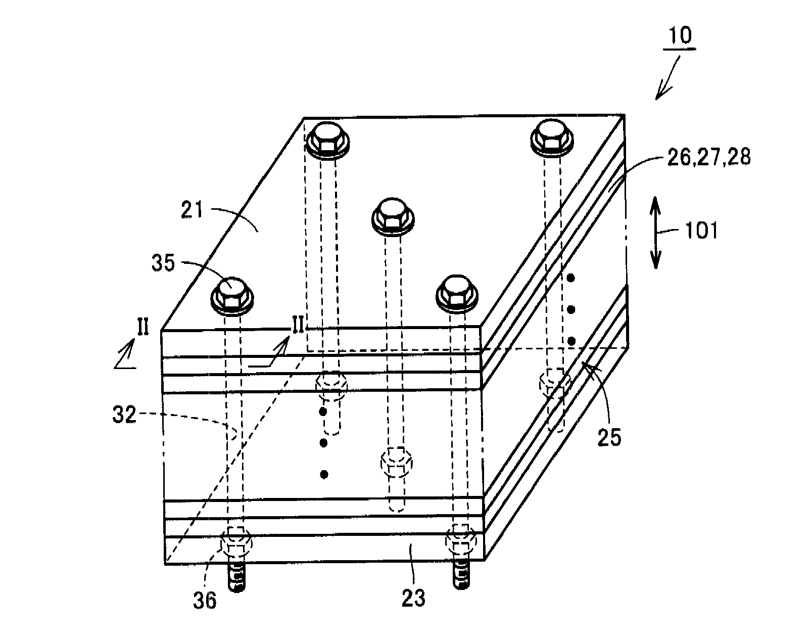
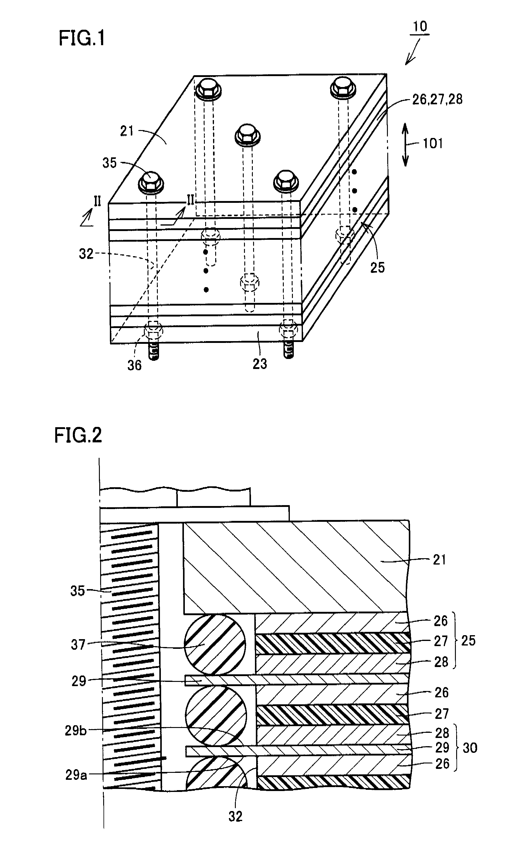
[0021]FIG. 1 is a perspective view showing a bipolar secondary battery to which the structure of the electrode stack in accordance with an embodiment of the present invention is applied. Referring to FIG. 1, a bipolar secondary battery 10 is mounted as an electric power supply in a hybrid vehicle using, as power sources, an internal combustion engine such as a gasoline engine or a diesel engine and a rechargeable electric power supply. Bipolar secondary battery 10 is formed of a lithium ion battery.

[0022]Bipolar secondary battery 10 is formed with a plurality of battery cells 25 stacked in the direction indicated by an arrow 101. Bipolar secondary battery 10 has an approximately rectangular parallelepiped shape. Bipolar secondary battery 10 may have a thin flat shape,...


PUM


Abstract

An electrode stack includes a cathode active material layer and an anode active material layer stacked together, and an electrolyte layer arranged between the cathode active material layer and the anode active material layer. A through hole extending in the stacking direction of the cathode active material layer and anode active material layer is formed in the cathode active material layer, anode active material layer and the electrolyte layer. The electrode stack further includes a bolt inserted to the hole for integrally holding the cathode active material layer, anode active material layer and the electrolyte layer. By such a structure, an electrode stack and a bipolar secondary battery that can effectively prevent displacement of interface between each of the cathode, anode and the electrolyte can be provided.

Description

TECHNICAL FIELD[0001]The present invention generally relates to an electrode stack and specifically to an electrode stack and a bipolar secondary battery using solid electrolyte or gel electrolyte.BACKGROUND ART[0002]In connection with a conventional electrode stack, by way of example, Japanese Patent Laying-Open No. 2004-47161 (Patent Document 1) discloses a secondary battery aimed at improving adhesion between battery elements and reducing expansion of the battery when gas generates. According to Patent Document 1, a battery element consisting of a cathode, an anode and a solid electrolyte is clipped by two plate members. The battery element and the plate members are integrally held by a tape wound around the plate members. In place of the tape, rubber, a band, a clip, a string or the like may be used.[0003]Japanese Patent Laying-Open No. 2004-31281 (Patent Document 2) discloses a cooling structure for an electrode-stacked type battery, in which the battery is pressed from opposit...

Claims


Application Information

Patent Timeline
IPC IPC(8): H01M4/06H01M4/13H01M10/04H01M10/05H01M10/0562H01M10/0565H01M10/0585
CPCH01M2/1083H01M2/1094H01M10/02H01M10/0418Y02E60/122H01M10/0562H01M10/0565H01M2300/0065H01M10/0481Y02E60/10H01M50/24Y02P70/50
Inventor TATEMATSU, KAZUTAKAMIZUTANI, RYOJIYAMADA, EIJIENDO, YASUHIRO
Owner TOYOTA JIDOSHA KK
Why Eureka
Try Eureka