High-Power Battery

Inactive Publication Date: 2009-02-12
MCGERVEY DONALD L +2
View PDF3 Cites 10 Cited by
  • Summary
  • Abstract
  • Description
  • Claims
  • Application Information

AI Technical Summary

Benefits of technology

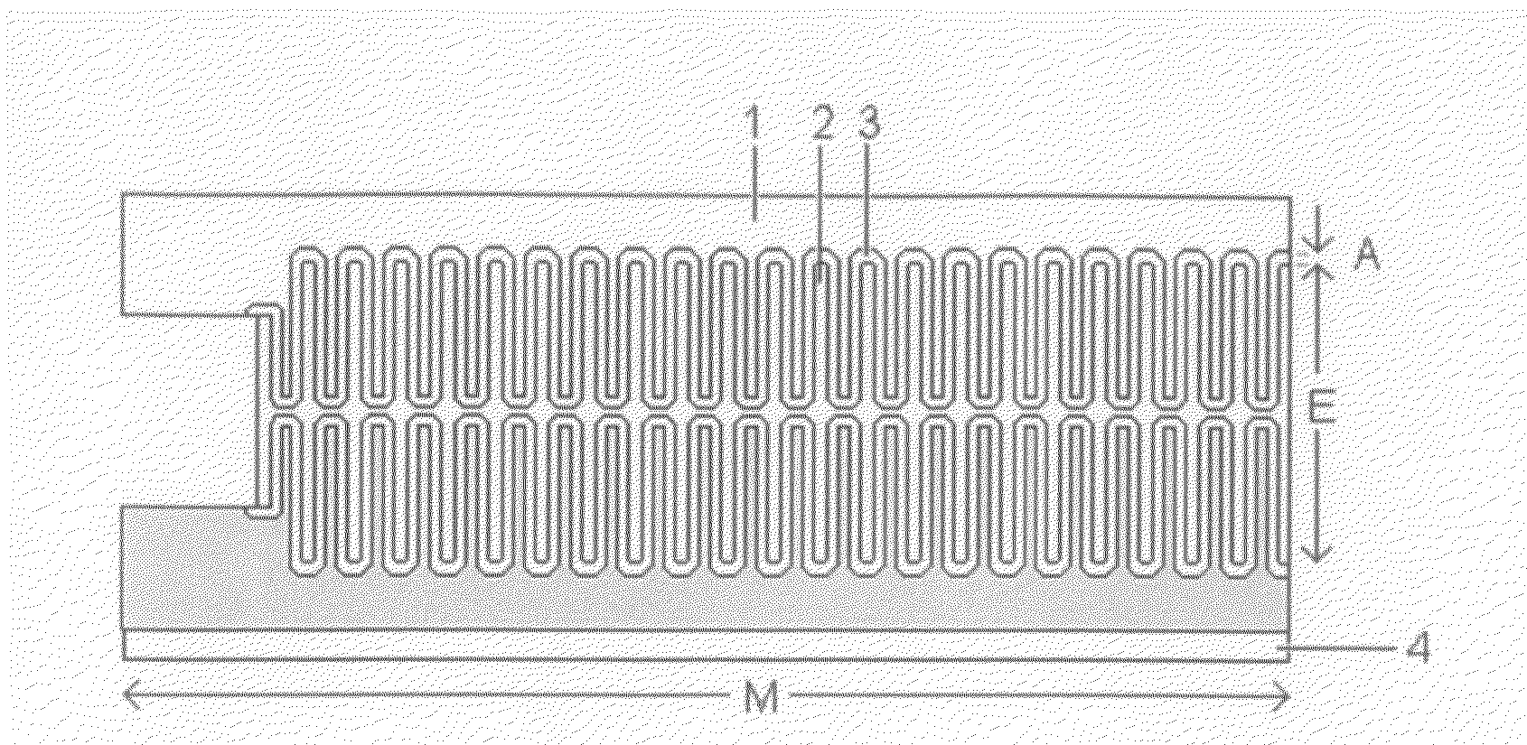
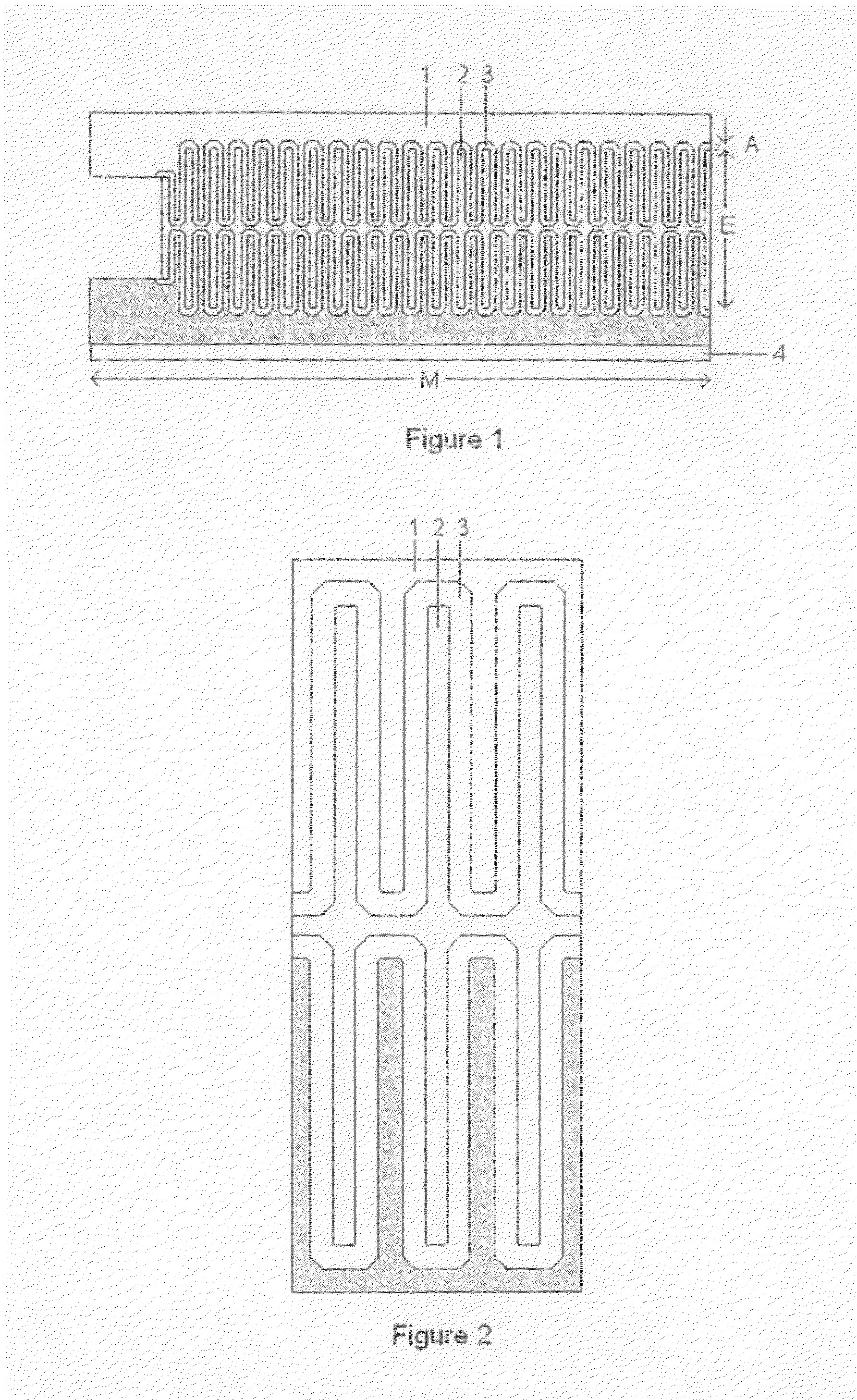
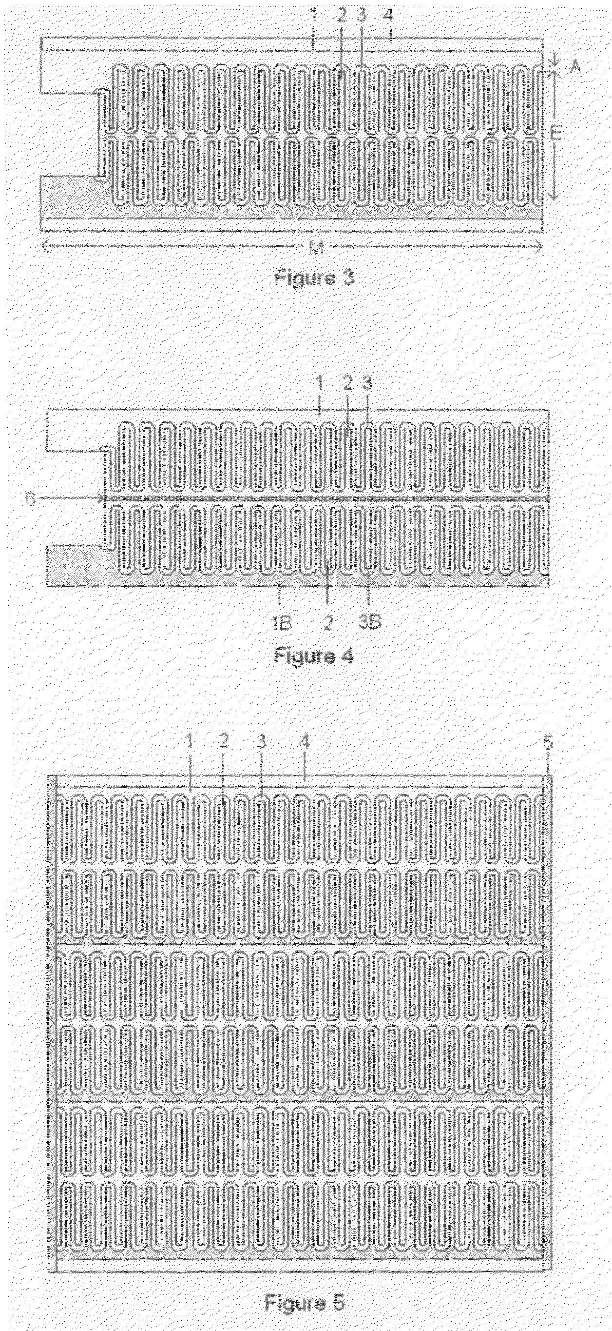
[0022]Our battery consists of a conductive anode material, e.g., a metal, an ‘anode active material’, an electrolyte, a conductive cathode material, e.g., a metal, and a ‘cathode active material’. Anode and cathode comprise a ‘metal backbone’ or a ‘metal spine’ with an open-porous metal layer or metal sponge of high surface area. The porous metal layer is relatively thin and comprises even thinner metal branches and open pores. The surface layer of the metal sponge is converted into a thin layer of active material by a chemical reaction.
[0023]The electrodes are arranged so that the anode surface i

Problems solved by technology

Prior art thin film batteries have not realized high volume fractions of active material

Method used


Image

  • High-Power Battery
  • High-Power Battery
  • High-Power Battery

Examples


example 1

[0045]Table 3 shows the resistances of active material of 1 cm3 volume of a comparison battery in which the active material is made (from a paste) with a layer thickness of 100 μm and a battery of the present invention in which the active material is an oxidation-formed layer of 50 nm thickness. The assumed resistivity ρ is 100,000Ω-cm for each active material. The ratios are of the thicknesses and resistances of the active materials in the comparison battery and the battery of the present invention. Batteries with lower series resistance have higher power.

TABLE 3ComparisonPresentbatteryinventionRatioActive material layer thickness100 μm 50 nm    2000:1Resistance R = ρ L2 / V 10 Ω2.5 μΩ4,000,000:1

example 2

[0046]Table 4 shows a comparison of electrodes of a thin-film battery with active material deposited on a flat substrate of 25 μm thickness and an electrode of a battery of the present invention with a metal sponge of 10 m2 surface area per cm3. Each electrode has an active material layer of 50 nm thickness. The total volume of each electrode is 1 cm3. The ratios show that the battery of the present invention has more active material per unit volume and therefore more energy and power than a prior art thin-film battery.

TABLE 4Thin-filmPresentbatteryinventionRatioArea of active material400 cm2 10 m21:250Volume of active material 2 mm3500 mm31:250

[0047]Batteries made by the present invention have the following unique characteristics:[0048]1. The electrodes of the battery have at least one side comprising high porosity metal sponge with interconnected dendrites or interconnected metal branches having small feature size and high specific surface area.[0049]2. The active material of the ...


PUM


Abstract

A method of forming battery electrodes with high specific surface and thin layers of active material is disclosed. The method enables low series resistance and high battery power.

Description

US PATENTS CITED[0001]G. P. Klein, U.S. Pat. No. 3,412,444 (1968)[0002]W. Mizushima et al., U.S. Pat. No. 4,041,359 (1977)[0003]J. Fife et al., U.S. Pat. No. 5,245,514 (1993)[0004]J. Bates et al. U.S. Pat. No. 5,338,625 (1994)[0005]X. Bi et al., U.S. Pat. No. 5,952,125 (1999)[0006]N. Bando et al., U.S. Pat. No. 5,965,295 (1999)[0007]G. Welsch and D. McGervey, U.S. Pat. No. 6,226,173 (2001)[0008]G. Welsch and D. McGervey, U.S. Pat. No. 6,495,021 (2002)[0009]S. Kawakami et al., U.S. Pat. No. 6,558,847 (2003)[0010]S. Nordlinder et al., U.S. Pat. No. 6,653,022 (2003)[0011]D. I. Ghantous and A. A. Pinoli, U.S. Pat. No. 7,198,869 (2007)REFERENCES CITED[0012]G. V. Samsonov (ed.) The Oxide Handbook, 2nd edition, IFI / Plenum Data Company (1982) 202-203[0013]E-S. Megahed et al. (eds.) The Electrochemical Society Proceedings Series PV 94-28 (1995)[0014]A. L. Tipton et al., J. Electrochemical Society, 143, Nov. 11 (1996) 3473-3477[0015]L. D. Kadan and P. S. Patil, Materials Chemistry and Physics...

Claims


Application Information

Patent Timeline
IPC IPC(8): H01M4/48H01M4/50H01M4/52H01M4/56H01M4/02H01M4/04H01M4/131H01M10/0525H01M10/36
CPCH01M4/0438H01M4/045H01M4/049H01M4/131H01M4/483Y02E60/122H01M10/0525H01M10/06H01M10/30H01M10/365H01M2004/021H01M4/745Y02E60/10
Inventor MCGERVEY, DONALD L.SZOZDOWSKI, PAUL T.WELSCH, GERHARD E.
Owner MCGERVEY DONALD L
Why Eureka
Try Eureka