Pattern forming method and mask

a pattern and mask technology, applied in the field of pattern forming methods and masks, can solve the problems of reducing the throughput of the exposure apparatus, wasting energy at the light-shielding portion, and limited application of pattern layouts

Inactive Publication Date: 2009-02-12
LONGITUDE LICENSING LTD
View PDF7 Cites 5 Cited by
  • Summary
  • Abstract
  • Description
  • Claims
  • Application Information

AI Technical Summary

Benefits of technology

[0024]According to the pattern forming method of the above aspect, since the resolution in the first direction in which the pitch is the smallest is obtained by the phase shifter and the resolution in the second direction in which the pitch is next smaller is improved by the oblique illumination, even if exposure is carried out using a mask with an asymmetrical layout, it is possible to prevent a pattern transferred onto a wafer from being largely deformed.
[0025]According to the mask of the above aspect, since the resolution in the first direction in which the pitch is the smallest and the resolution in the third direction defined by the pitches in the first and second directions are obtained by the phase shifter, the above advantage is obtained by performing exposure using this mask in the above pattern forming method.

Problems solved by technology

However, if the metal diaphragm is used in the oblique illumination, energy at a light-shielding portion is wasted and thus there may arise a problem of reduction in throughput of an exposure apparatus.
Therefore, in the four-point illumination, applicable pattern layouts are limited.
The two-point illumination can achieve the greatest resolution improving effect for patterns along one direction as compared with the foregoing annular illumination and four-point illumination, but may have difficulty in resolving other patterns.
Therefore, it has been difficult to apply the two-point illumination to device circuit patterns.
This is because, although the oblique illumination has the drawback that the contrast is reduced due to poor balance between a zero-order beam and one of ±first-order beams, the contrast can be improved by reducing the zero-order beam using the halftone phase shift mask.
The present inventor has recognized that, if the strong super-resolution techniques such as the Levenson phase shift mask and the two-point illumination are used, there arises a problem that a pattern transferred onto a wafer is largely deformed depending on a pattern layout formed on the mask.
Particularly, in the case of the Levenson phase shift mask, although a high contrast can be obtained between openings with opposite phases, it cannot be obtained in a layout where openings with the same phase are close to each other, so that patterns cannot be separated.
Therefore, if the Levenson phase shift mask is applied to an asymmetrical layout, separation between the openings with the same phase cannot be achieved and thus a pattern transferred onto a wafer is largely deformed.
Patent Document 1 aims to improve the resolution of one-dimensional patterns, but fails to consider preventing deformation of two-dimensional patterns.

Method used


Image

  • Pattern forming method and mask
  • Pattern forming method and mask
  • Pattern forming method and mask

Examples


first embodiment

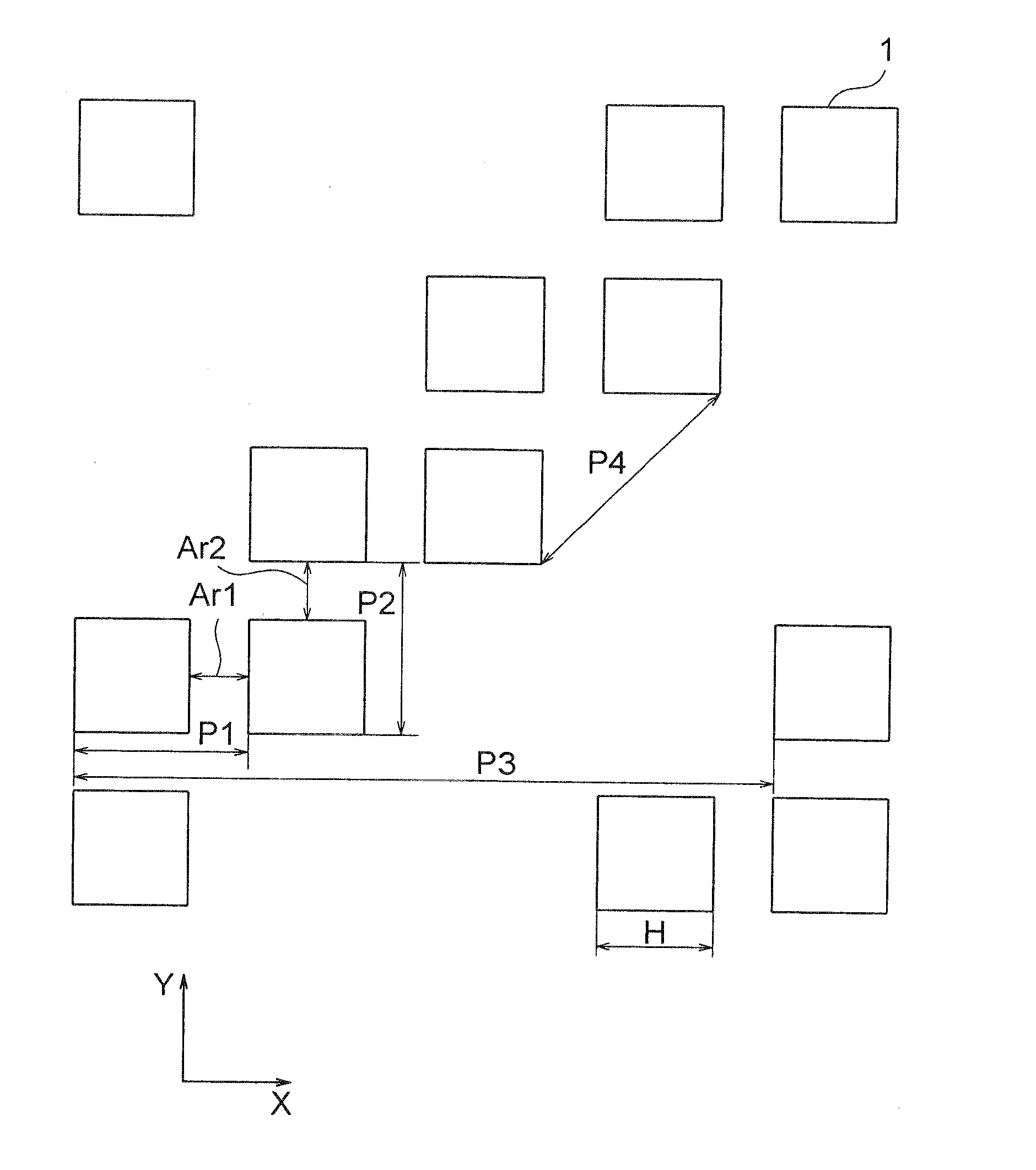
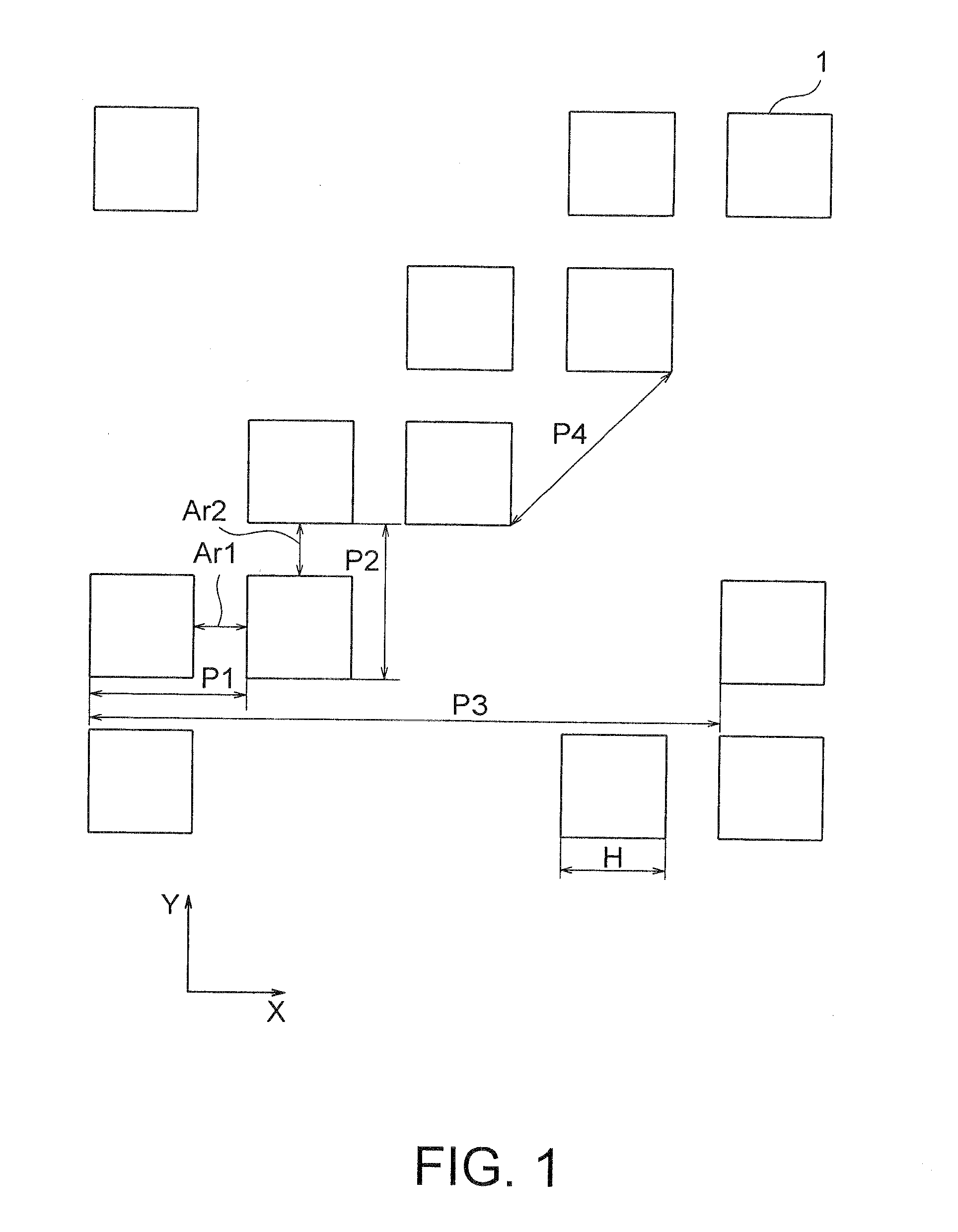
[0043]FIG. 1 is a plan view showing a layout of a mask used in a pattern forming method according to this invention.

[0044]In FIG. 1, hole patterns 1 are each, for example, a square pattern and are repeated at a constant pitch in an oblique direction inclined by 45 degrees with respect to the X-direction, and arranged in every two rows. That is, the layout of this mask is an asymmetrical layout. Herein, the layout of the mask is shown as CAD data of the hole patterns 1. Hereinbelow, the pitch represents a magnitude of a vector obtained by resolving a vector, with its initial and terminal points at the centers of two patterns along a direction in which patterns are repeated, in one of the X-direction, the Y-direction, and the oblique direction, for example.

[0045]In the pattern forming method of the first embodiment, using a mask having a Levenson phase shifter formed for the hole patterns 1 arranged in a direction in which the pitch is the smallest, exposure is performed by two-point ...

second embodiment

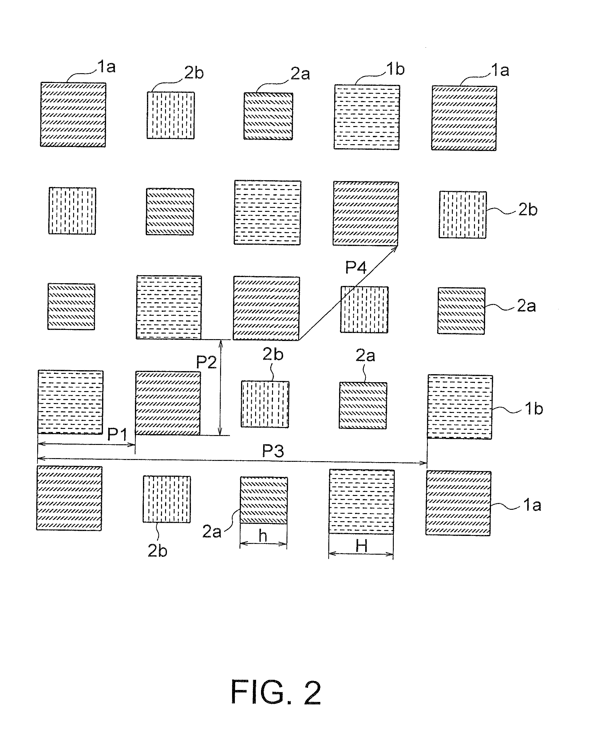
[0054]FIG. 6 is a plan view showing a layout of a mask used in a pattern forming method according to this invention. The layout of the mask shown in FIG. 6 is an asymmetrical layout in which a pitch P1 of hole patterns 1 adjacent to each other in the X-direction is greater than that in the asymmetrical layout shown in FIG. 1. Specifically, in this layout, the pitch P1 of the adjacent hole patterns 1 in the X-direction is set to 180 nm, while, a pitch P2 of the adjacent hole patterns 1 in the Y-direction is set to 140 nm equal to that in FIG. 1 and a pitch P3 per two rows of the hole patterns 1 is set to 560 nm equal to that in FIG. 1. Herein, the pitch P2 represents a magnitude of a vector C obtained by resolving a vector, with its initial point at the center B of the hole pattern 1b and its terminal point at the center A of the hole pattern 1a in FIG. 6, in the Y-direction. A mask size H of each hole pattern 1 is for forming a hole of 80 nm on a wafer and is set to 90 nm in conside...


PUM

PropertyMeasurementUnit
sizeaaaaaaaaaa
sizeaaaaaaaaaa
sizeaaaaaaaaaa

Abstract

Hole patterns are repeatedly arranged on a mask at a constant pitch in each of predetermined directions. In the predetermined directions, a first direction with the smallest pitch and a second direction with the second smaller pitch are specified. A Levenson phase shifter is formed corresponding to the hole patterns to cause the phases of transmitted light through the hole patterns adjacent to each other in the first direction to be opposite to each other. An exposure process is performed by two-point illumination which is adapted to improve the resolution property in the second direction.

Description

[0001]This application is based upon and claims the benefit of priority from Japanese patent application No. 2007-204509, filed on Aug. 6, 2007, the disclosure of which is incorporated herein in its entirety by reference.FIELD OF THE INVENTION[0002]This invention relates to a pattern forming method and a mask and, more specifically, relates to a pattern forming method for forming a pattern corresponding to a mask on a semiconductor wafer and to the mask used in this method.DESCRIPTION OF RELATED ART[0003]The current photolithography technology enables the formation of a fine pattern with a width equal to or less than half an exposure wavelength by the application of a super-resolution technique. The super-resolution technique is a technique for improving the resolution by optimizing the shape of a mask illumination light source, the amplitude distribution of mask-transmitted light, or the amplitude distribution on the pupil plane. An exposure master formed with a device circuit patt...

Claims


Application Information

Patent Timeline
Patent Type & Authority Applications(United States)
IPC IPC(8): G03F1/00G03F7/22G03F1/30G03F1/36G03F1/70H01L21/027
CPCG03F1/30
Inventor YASUZATO, TADAO
Owner LONGITUDE LICENSING LTD
Why Eureka
Try Eureka