Solar panel

a solar panel and panel technology, applied in the field of solar panels, can solve the problems of inconvenient mounting on curved surfaces, inflexible mono- and polycrystalline photovoltaic cells, and inability to bend easily, so as to achieve the effect of not affecting the flexing of the panel

Inactive Publication Date: 2009-02-19
ZETA CONTROLS LTD
View PDF3 Cites 24 Cited by
  • Summary
  • Abstract
  • Description
  • Claims
  • Application Information

AI Technical Summary

Benefits of technology

[0013]The polymeric support element is preferably made of polyethylene terephthalate (PET), which is durable, UV stable, weatherproof and does not affect the performance of the photovoltaic cells. Other suitable materials may also be used.
[0014]Advantageously, the photovoltaic cells are embedded in the polymeric support element. This provides a degree of protection for the photovoltaic cells while not significantly affecting their efficiency.
[0016]This arrangement ensures that even if some of the cells are unable to generate efficiently (for example, because they are damaged or shaded from the sun), the generating efficiency of the other cells is not affected.
[0018]Advantageously, the bypass diodes are mounted externally of the cells and are preferably embedded in the substrate. This provides a compact, space saving product and does not impede flexing of the panel.

Problems solved by technology

Such photovoltaic cells are, however, relatively inefficient, generating only about 50% of the power generated by mono- or poly-crystalline photovoltaic cells of the same size.
However, mono- and poly-crystalline photovoltaic cells are not flexible and crack easily if bent.
They are not suitable therefore for mounting on curved surfaces.
A problem with existing solar panels is that if one or more of the cells is damaged or non-operational (for example, if it is shaded from the sunlight), the impedance of that cell will greatly reduce the output of the entire panel.

Method used


Image

  • Solar panel
  • Solar panel
  • Solar panel

Examples


Embodiment Construction

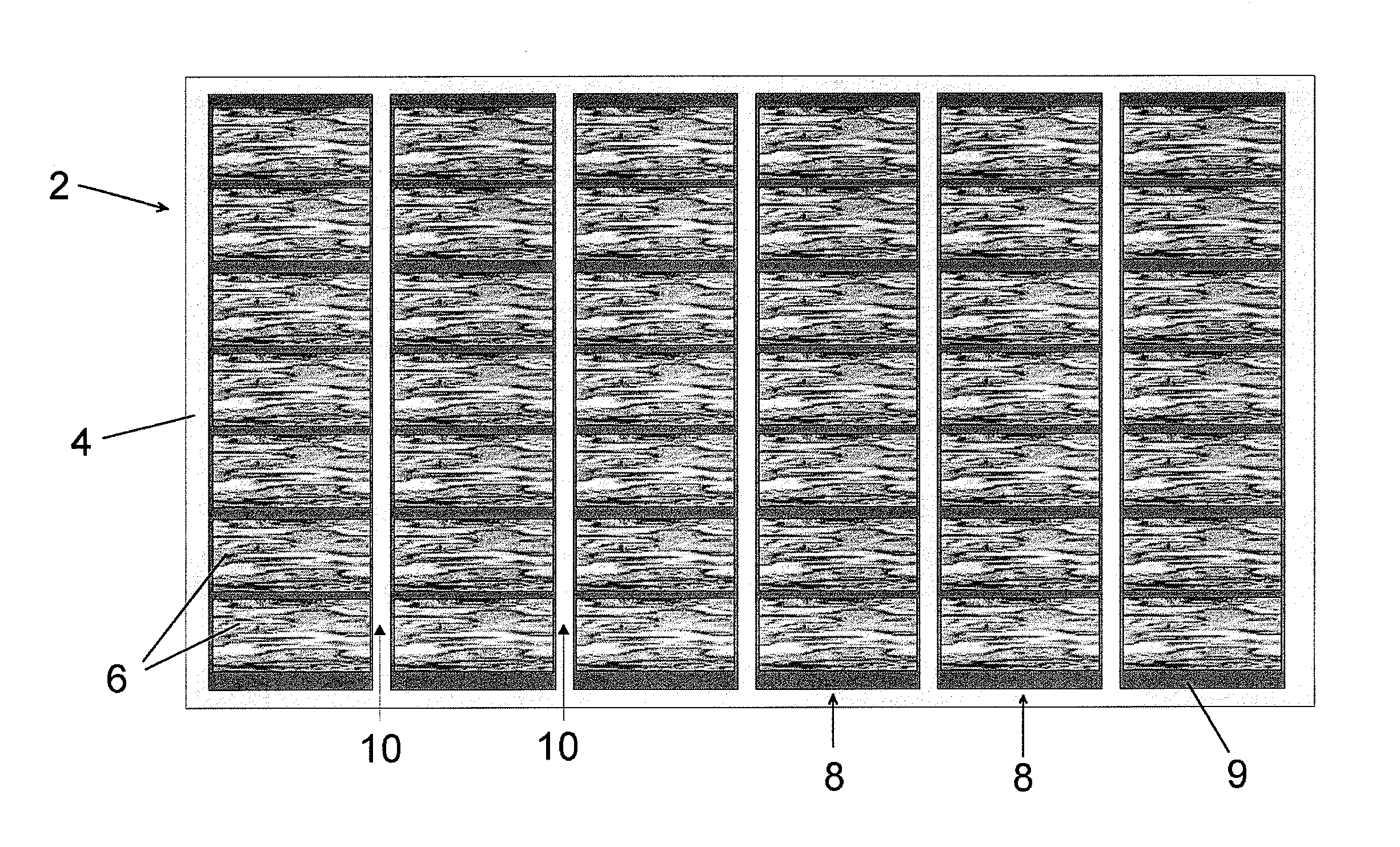
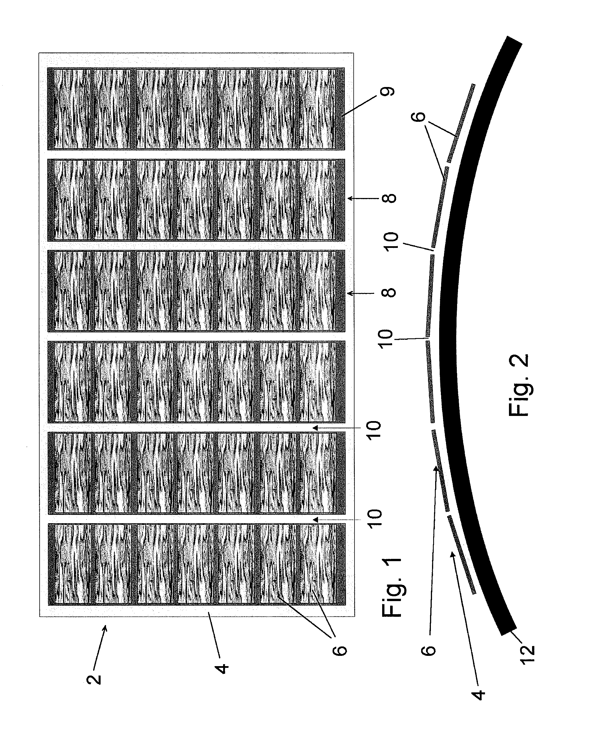
[0029]The solar panel 2 shown in FIG. 1 includes a rectangular support element 4 that is made of a flexible polymeric material, for example polyethylene terephthalate (PET). The support element supports a two-dimensional array of photovoltaic cells 6, which are embedded within the polymeric material of the support element 4. The cells 6 are arranged in six parallel rows 8, each row containing seven cells on a printed circuit board substrate 9 of fiberglass (e.g. FR4). The PCB substrate 9 carries the electrical connections (not shown) to the cells 6.

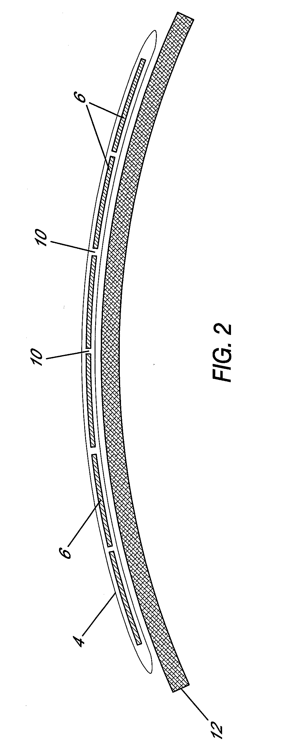
[0030]The parallel rows of cells 6 are spaced apart with 2 mm gaps between adjacent rows 8. The flexible polymeric support element provides a plurality of parallel flexible hinges 10 in the gaps between the spaced apart rows 8. The hinges 10 allow the solar panel 2 to flex without excessively bending or stressing the individual cells 6. This allows the panel 2 to be mounted on a curved mounting surface 12, for example the roof of a bus sh...


PUM


Abstract

A solar panel including a flexible polymeric support element and a plurality of photovoltaic cells supported by the support element. At least some of the photovoltaic cells are spaced apart such that the flexible support element provides a hinge between the spaced apart photovoltaic cells. A plurality of bypass diodes are connected in parallel with the cells, so that if one of the cells ceases to operate, electrical current generated by the other cells is able to bypass the inoperative cell.

Description

BACKGROUND OF THE INVENTION[0001]1. Field of the Invention[0002]The present invention relates to a solar panel. In one aspect, the invention relates to a solar panel that is suitable for mounting on a curved surface, and in another aspect to a solar panel that is not excessively affected by reduced or non-operation of one or more solar cells.[0003]2. Background of the Invention[0004]Solar panels are sometimes mounted on curved surfaces such as the roofs of bus shelters and are used to generate electricity for lighting, signage and other purposes. In such situations, photovoltaic cells made of amorphous silicon are generally used as they are flexible and can be bent to fit the curved surface. Such photovoltaic cells are, however, relatively inefficient, generating only about 50% of the power generated by mono- or poly-crystalline photovoltaic cells of the same size. However, mono- and poly-crystalline photovoltaic cells are not flexible and crack easily if bent. They are not suitable...

Claims


Application Information

Patent Timeline
Patent Type & Authority Applications(United States)
IPC IPC(8): H01L31/048H01L31/042
CPCH01L31/02008Y02E10/50H01L31/048H01L31/042H01L31/0504H01L31/044
Inventor SHADBOLT, PHILIP DAVIDTYRRELL, PAUL JOHN
Owner ZETA CONTROLS LTD
Why Eureka
Try Eureka