
Scanning Spectrometer With Multiple Photodetectors

a scanning spectrometer and photodetector technology, applied in the field of spectrometers, can solve the problems of reducing the overall reliability and expected lifetime of the conventional scanning opm, being subject to stringent industrial requirements, and being bulky and expensiv

Active Publication Date: 2009-02-19
LUMENTUM OPERATIONS LLC
View PDF6 Cites 32 Cited by
  • Summary
  • Abstract
  • Description
  • Claims
  • Application Information

AI Technical Summary

Benefits of technology

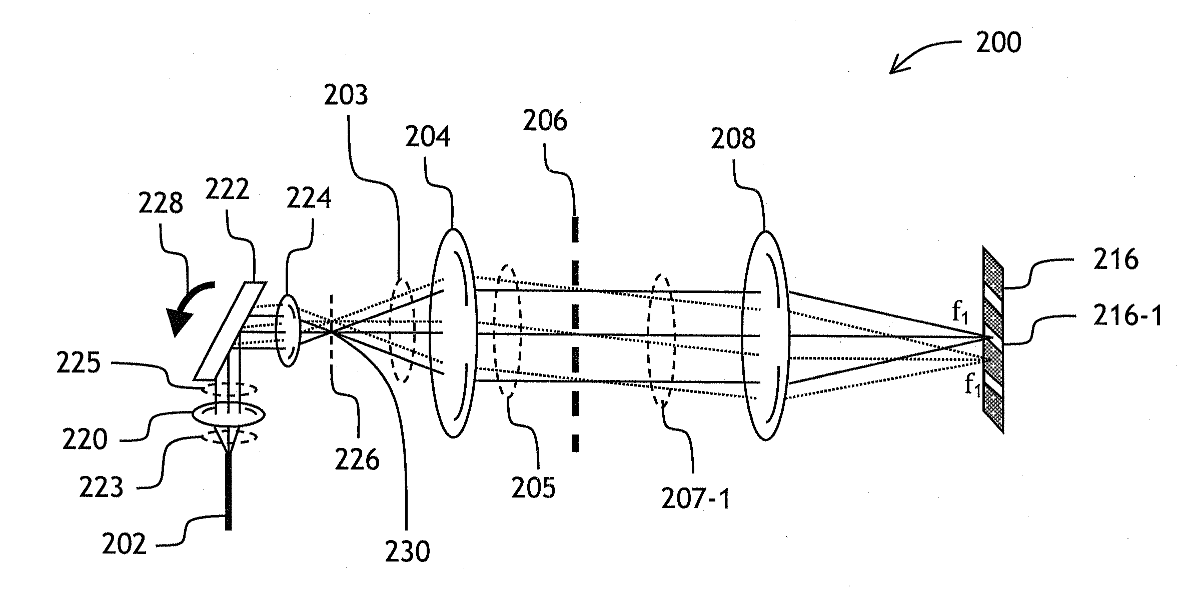
[0016]It is an object of the present invention to provide a spectrometer combining the advantages of both scanning and detector array-based approaches. The spectrometer of the present invention provides a high-fidelity, scanned optical spectrum, with a number of measurement points not limited by the apparatus geometry. Further, advantageously, the spectrometer of the present invention uses parallel detection, with much less light being discarded for spectral selectivity than in a prior-art scanning approach described above. Yet further, advantageously, the spectrometer of the present invention allows for multiple selectable input ports without an associated increase in complexity, e.g. without having to incorporate an additional switch at the input, which leads to significant cost savings for a system requiring multiport spectral measurements.

Problems solved by technology

Furthermore, they are generally bulky as well as costly.
Optical communication systems require industrial grade optical performance monitors (OPMs), which function similarly to the traditional OSA, but are, however, subject to stringent industrial requirements.
Moreover, having to rotate a relatively large optical element such as diffraction grating reduces overall reliability and expected lifetime of a conventional scanning OPM.
Disadvantageously, the number of photodiodes in the PDA scales proportionally to the required wavelength resolution, thereby increasing the size and cost of the device and reducing its reliability.
Disadvantageously, when the optical channel density is increased, the crosstalk between the input waveguides effectively limits amount of data points available.
Detrimentally, the approach of Shen et al., due to Vernier geometry, produces a set of folded spectra and therefore requires computation-intensive spectral unfolding processing.
Further, for both approaches of Berolo et al. and Shen et al., an external waveguide-coupled optical switch is required which complicates the design and increases optical losses.

Method used


Image

  • Scanning Spectrometer With Multiple Photodetectors
  • Scanning Spectrometer With Multiple Photodetectors
  • Scanning Spectrometer With Multiple Photodetectors

Examples


Embodiment Construction

[0044]While the present teachings are described in conjunction with various embodiments and examples, it is not intended that the present teachings be limited to such embodiments. On the contrary, the present teachings encompass various alternatives, modifications and equivalents, as will be appreciated by those of skill in the art.

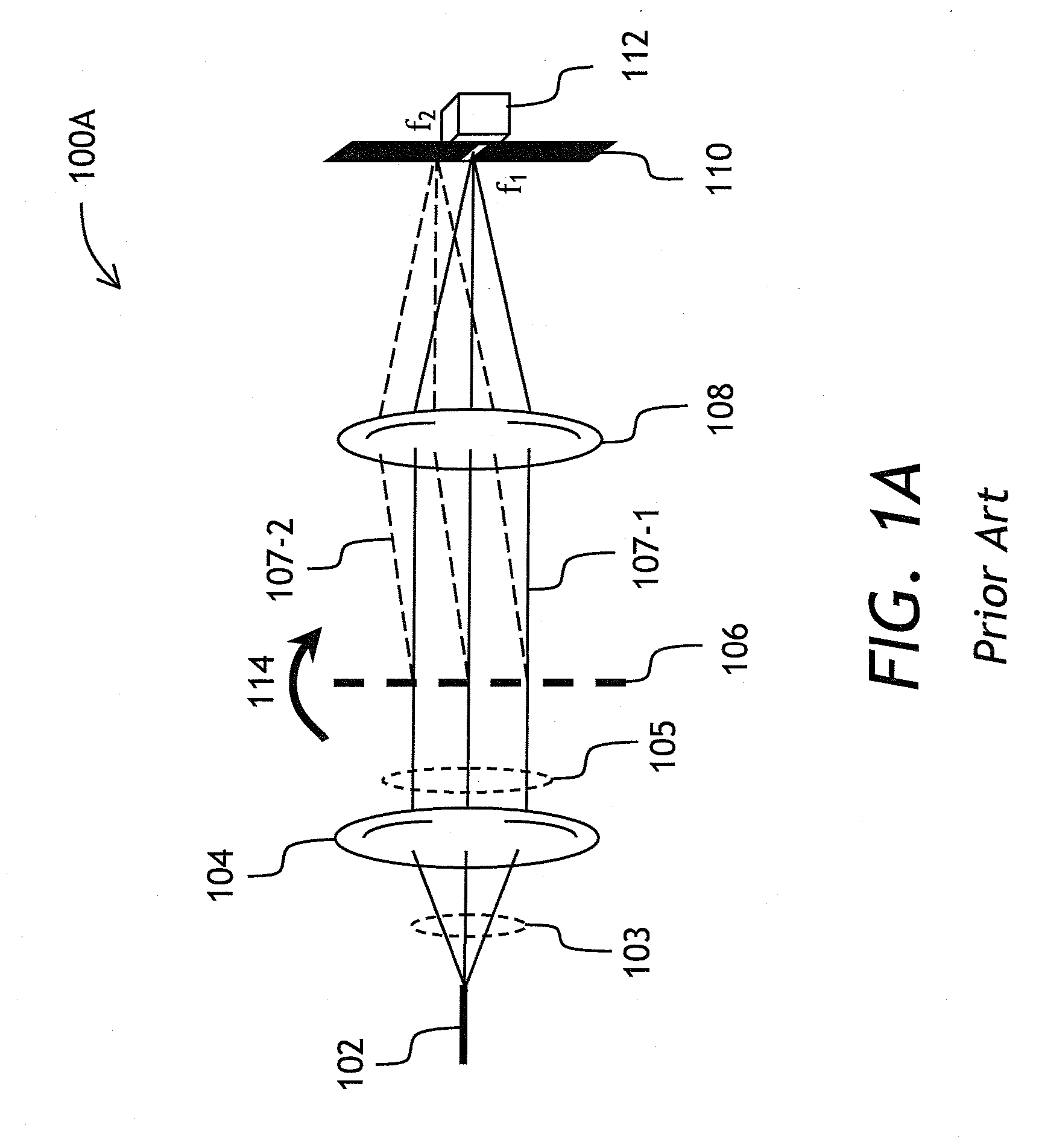
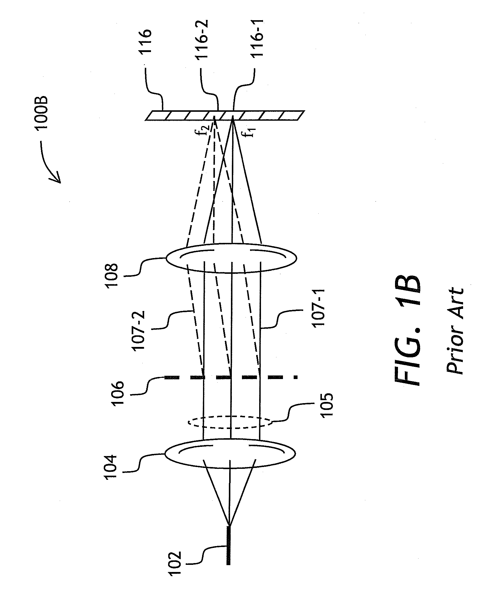
[0045]Referring to FIG. 1A, a view of a conventional scanning spectrometer 100A is shown comprising an input port 102, a collimating lens 104, a diffraction grating 106, a focusing lens 108, a slit 110, and a detector 112. The input port 102 representing an input slit or an input waveguide defines the starting point of a diverging light beam 103, which is collimated by collimating lens 104 to produce a collimated beam 105. The beam 105 impinges onto diffraction grating 106, which disperses the beam into a fan of individual monochromatic beams. For example, a beam 107-1 at an optical frequency f1 propagates to the lens 108 straight, and a beam 107-2 at an ...


PUM


Abstract

A scanning optical spectrometer with a detector array is disclosed, in which position of focused spot of light at the input of a dispersive element such as arrayed waveguide grating (AWG) with a slab input, is scanned using a micro-electro-mechanical (MEMS) tiltable micromirror so as to make the dispersed spectrum of light scan over the detector array coupled to the AWG. Sub-spectra recorded using individual detectors are concatenated by a processor unit to obtain the spectrum of input light.

Description

CROSS-REFERENCE TO RELATED APPLICATIONS[0001]The present invention claims priority from U.S. patent application Ser. No. 60 / 955,455 filed Aug. 13, 2007, entitled “Scanning MEMS and grating based optical performance monitor”, by Crafts et al., which is incorporated herein by reference for all purposes.TECHNICAL FIELD[0002]The present invention is related to spectrometers, and in particular to optical performance monitors in a fiberoptic network.BACKGROUND OF THE INVENTION[0003]A spectrometer is an apparatus for measuring a spectrum of electromagnetic radiation such as light. Spectrometers are widely used in science and industry as powerful analytical and measurement tools. For example, they are used for remote sensing of temperature, determining chemical composition and concentration of chemical compounds, and identifying substances.[0004]Spectrometers for measuring optical power as a function of wavelength are called optical spectrum analyzers (OSAs). Most conventional OSAs use a wa...

Claims


Application Information

Patent Timeline
IPC IPC(8): G01J3/28
CPCG01J3/18G02B6/12019G01J3/2803
Inventor CRAFTS, DOUGLAS E.SHEN, JINXIDUGGAN, PHILIPFARRELL, JAMES F.FONDEUR, BARTHELEMYRANALLI, ELISEO
Owner LUMENTUM OPERATIONS LLC
Learn More