Lighting Apparatus With Leds

a technology of led lights and led tubes, which is applied in the direction of lighting and heating apparatus, fixed installation, semiconductor devices for light sources, etc., can solve the problems of thermally conductive performance not being sufficient and the cost of mounting the circuit board, so as to reduce the cost of the circuit board, and reduce the effect of temperature ris

Active Publication Date: 2009-02-19
MATSUSHITA ELECTRIC WORKS LTD
View PDF14 Cites 83 Cited by
  • Summary
  • Abstract
  • Description
  • Claims
  • Application Information

AI Technical Summary

Benefits of technology

[0005]In view of the above problem, the present invention has been achieved to provide a lighting apparatus with light emitting diodes (LEDs) which is capable of suppressing temperature rise in the LED chip to realize a high light output and reduce a cost of circuit board. The lighting apparatus according to the present invention includes a metal-made main body 90; a plurality of LED chip units 1 each including an LED chip and a pair of lead terminals 42, 43 electrically connected to electrodes of the LED chip; and a dielectric layer 80 disposed between the main body 90 and the LED chip units 1 for making electrical insulation as well as thermally conductive coupling therebetween. The circuit board 20 is formed with a plurality of windows 23 through which the individual LED chip units 1 extend respectively with the lead terminals held in electrical contact with a circuit pattern 22, each of the LED chip units being thermally coupled at its bottom face with the main body 90 through the dielectric layer 80. With this arrangement, the dielectric layer 80 can transfer a heat from the LED chip to the main body not through the circuit board, enabling to reduce a thermal resistance between a light emitting part of the LED chip and the main body for enhancing the thermally conductive performance and suppressing a rise in the junction temperature of the LED chip. Therefore, an input electric power can be increased for achieving the high light output, compared to a prior art. Furthermore, it is also enabled to adopt less expensive circuit board, such as glass epoxy board, as the circuit board than a metal board, without any consideration of its ability to radiate the heat, thereby reducing the cost of the circuit board.
[0006]Preferably, each of the LED chip units has its bottom face defined by the lead terminals 42, 43 which are mounted on the dielectric layer 80, so that the heat generated in the LED is efficiently conducted to the main body through the dielectric layer from the lead terminals.
[0007]The lighting apparatus is preferably formed with a light-transmissive member 91, 200 to pass a visible light from each of the LED chip units 1, and a mirror 24 is formed on a top face of the circuit board 20 opposed to the light-transmissive member for reflecting the visible light. With this arrangement, the mirror can reflect the visible light suffering from a total reflection by the light-transmissive member after radiated from each of the LED chip units 1, enabling to enhance the light output.

Problems solved by technology

Thus, a metal-made heat radiative board is necessarily attached to the bottom surface of the circuit board for enhancing thermally conductive performance over a whole range of circuit board, thereby mounting a cost of the circuit board.
In this case, however, the thermally conductive performance can not be sufficiently made due to two dielectric layers, dielectric layer of the circuit board and the dielectric sheet, interposed on thermally conductive path from the LED chip to the metal-made main body through the circuit board.

Method used


Image

  • Lighting Apparatus With Leds
  • Lighting Apparatus With Leds
  • Lighting Apparatus With Leds

Examples


first embodiment

[0046]Hereafter, the lighting apparatus of the present embodiment will be described with reference to FIGS. 1 to 5.

[0047]The lighting apparatus of the present embodiment is used as a spot light or the like. A main body 90 is made of a metal, high thermally conductive metal such as Al and Cu, and attached by means of a bonding screw 113 to an arm 112. The arm is fixed at its one end by a shaft screw 111 to a rotatable base 110 on a supporting base 100.

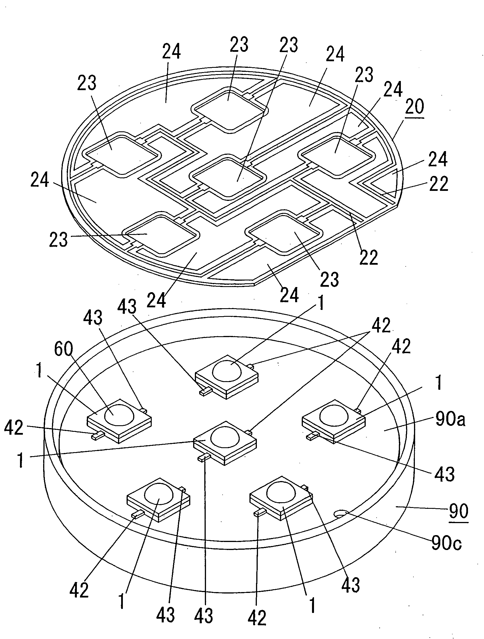
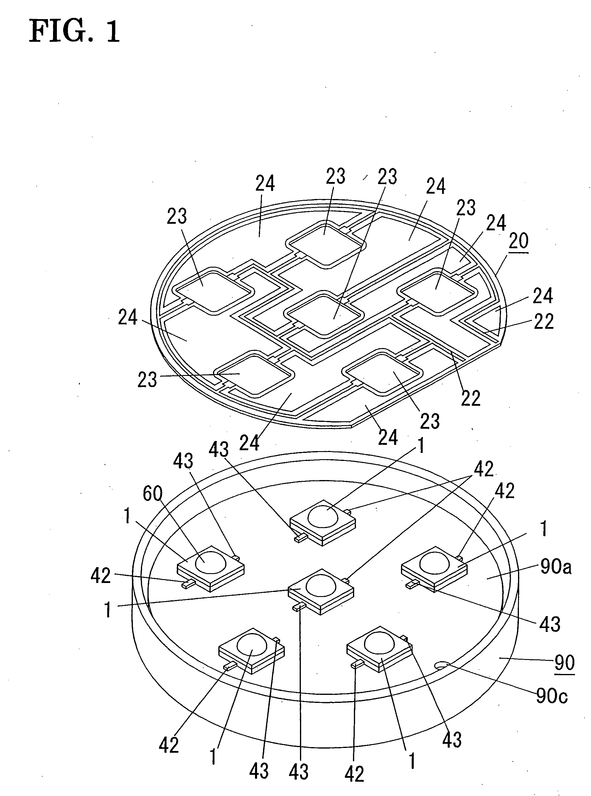
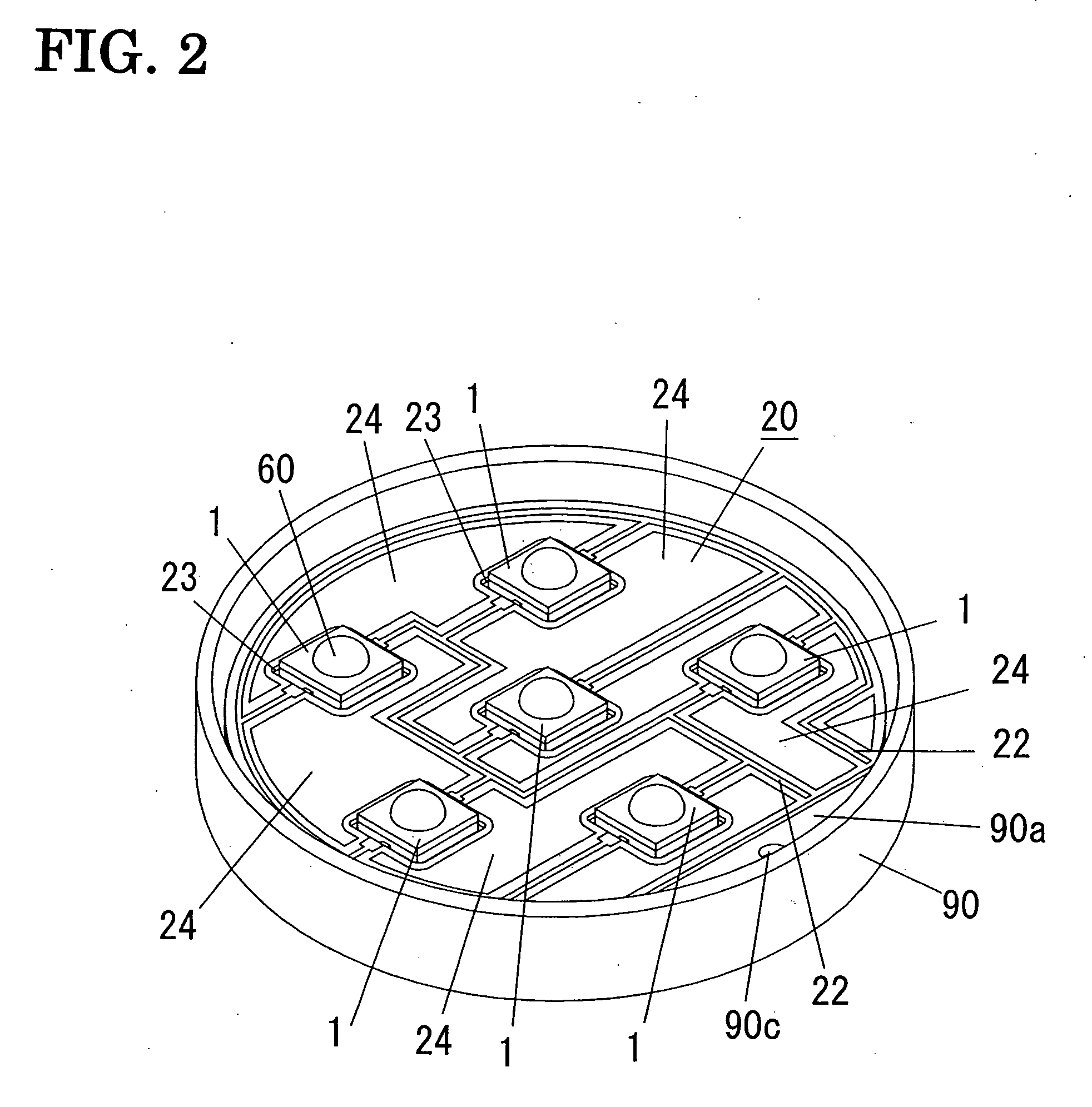
[0048]The main body 90 is shaped into a bottomed tube (a bottomed cylindrical tube in the present embodiment) with an opened surface (front surface) to accommodate a plurality of LED chip units 1 (light emitting devices). In the present main body 90, each of the LED chip units 1 is mounted to a bottom wall 90a through a dielectric layer 80 made of a green sheet, and the opened surface is covered with a front cover 91. The front cover 91 includes a disk-shaped light-transmissive plate 91a made of glass plate, and a ring-shaped window fra...

second embodiment

[0071]The light apparatus with LED of this embodiment has almost the same configuration as that of first embodiment. As shown in FIGS. 6 to 8, the LED chip unit 1 in the present embodiment is different from that of first embodiments. Like components as that of the first embodiment are designated by like reference numerals, and no duplicate explanation deemed necessary. The front cover 91 (see FIG. 4) is provided in this embodiment as well as the first embodiment.

[0072]Instead of the chip mounting member 41, the respective lead terminals 42, 43, and the holding frame 45 used in the first embodiment, the present embodiment employs a mounting board (chip mounting member) 70 which is composed of a rectangular plate-shaped conductive plate 71 carrying on its surface the LED chip 10, and a dielectric film 72 superimposed on the conductive plate 71 and being formed on its surface with patterned lead terminals 73, 73 respectively for connection with the anode and cathode electrodes of the L...

third embodiment

[0078]The configuration of a lighting apparatus with LEDs in the present embodiment is almost the same as that in first embodiment. The configuration of the circuit board 20 in the present embodiment is different from that in first one, as shown in FIGS. 9 to 11. Like components as that of the first embodiment are designated by like reference numerals, and no duplicate explanation deemed necessary. The front cover 91 (see FIG. 4) is provided in this embodiment as well as the first one.

[0079]In this embodiment, the circuit pattern 22 extends from one surface to the other surface of the circuit board 20 opposing the light-transmissive plate 91a (see FIG. 4) through the periphery of the window 23 to form thereof a bonding area 95 where the circuit pattern 22 is electrically connected to lead terminals 42, 43 of the LED chip unit by bonding material such as a solder.

[0080]Compared to the first embodiment, the lighting apparatus with LEDs of this embodiment can be formed so as to enlarge...


PUM


Abstract

A lighting apparatus with LED includes a metal-made main body 90; a plurality of LED chip units 1 each including an LED chip and a pair of lead terminals 42, 43 electrically connected to electrodes of the LED chip; and a dielectric layer 80 disposed between the main body 90 and each LED chip unit 1 for making electrical insulation therebetween as well as bond the same. The circuit board 20 is formed with a plurality of windows 23 through which the individual LED chip units 1 extend respectively with the lead terminals held in electrical contact with the circuit pattern of the circuit board at the circumference of the window, each of the LED chip units being thermally coupled at its bottom face with the main body 90 through the dielectric layer 80, and the heat generated in the LED chip is conducted to the main body through the dielectric layer without passing through the circuit board.

Description

TECHNICAL FIELD[0001]The present invention relates to a lighting apparatus with LEDs (light emitting diodes).BACKGROUND ART[0002]The research of light emitting device has been widely carried out and developed so far by utilizing an LED chip and a phosphor (fluorescent pigment, fluorescent dye, or the like) acting as wavelength conversion material which is excited by a light from the LED chip to emit a light of a color different from a luminescent color of the LED chip. The light emitting device enables to emit a light of a color different from the luminescent color of the LED chip by combining the LED chip with the phosphor, leading to commercialization of a white light emitting device (generally referred to as white LED) and the like. The white light emitting device emits a white light (light emission spectrum of white light) by a combination of the phosphor with the LED chip emitting a blue color light, an ultraviolet light, or the like.[0003]As the output of the LED chip is incre...

Claims


Application Information

Patent Timeline
Patent Type & Authority Applications(United States)
IPC IPC(8): F21V7/00H01L33/62H01L33/64
CPCF21K9/00F21Y2101/02H01L33/62H01L33/64H01L2224/48091H01L2224/73265H01L2924/01079H01L2924/19041H05K1/0203H05K1/182F21S4/003F21V23/002F21V29/20H01L2224/45144H05K1/021H01L2924/01019H05K2201/10106H01L2924/00014H01L2924/00F21S4/20F21Y2115/10F21V29/70F21V19/00F21S8/04
Inventor URANO, YOUJINAKATANI, TAKUYAHIDAKA, YASUHIROGOTO, YOSHIRO
Owner MATSUSHITA ELECTRIC WORKS LTD
Why Eureka
Try Eureka