Road and rail vehicle and track therefor

a technology for road and rail vehicles and tracks, applied in the direction of underwater vessels, railway system combinations, non-deflectable wheel steering, etc., can solve the problems of difficulty in transiting between road and rail, and prone to derailment of tandem road and rail systems, so as to reduce noise

Inactive Publication Date: 2009-02-26
HEFEI BOPU HIGH TECH
View PDF23 Cites 23 Cited by
  • Summary
  • Abstract
  • Description
  • Claims
  • Application Information

AI Technical Summary

Benefits of technology

[0030]1. Running resistance is greatly reduced, and power consumption and pollution discharge are decreased by 50-70%;
[0031]2. Convenient switching between the road and the railway saves time and money;
[0032]3. Use of tires greatly improves pulling force of the vehicle;

Problems solved by technology

However, tandem road and rail vehicles have had only limited success and are much less common than separate road vehicles and rail vehicles.
Part of the problem with building tandem road and rail system lies in the difficulty of transiting between road and rail, and vice versa.
In addition, tandem road and rail system are prone to derailments and suffer from high wind resistance, and traffic control difficulties.

Method used


Image

  • Road and rail vehicle and track therefor
  • Road and rail vehicle and track therefor
  • Road and rail vehicle and track therefor

Examples


example 1

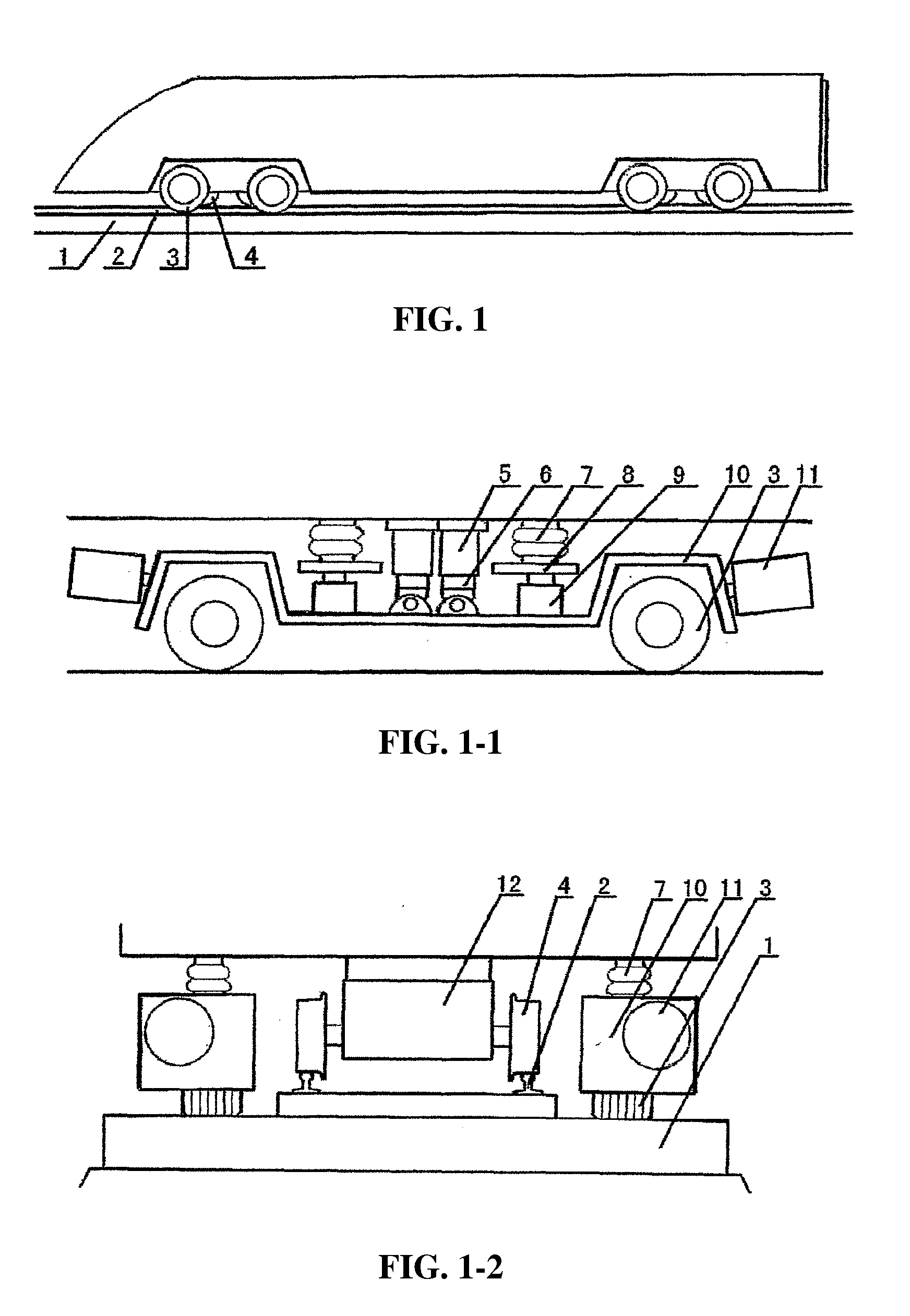
[0069]As shown in FIG. 1, a road and rail vehicle of the invention comprises a plurality of tires 3 and rail wheels 4. The rail wheels 4 travel on a railway track 2, and the tires 3 travel on a road 1 disposed on both sides of the railway track 2.

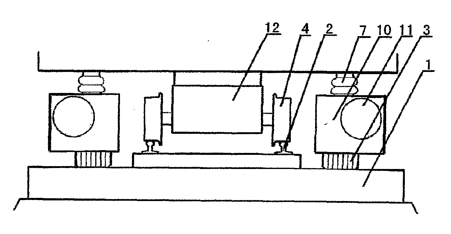
[0070]As shown in FIG. 1-1, a pair of tire carriers 10 is disposed below the road and rail vehicle via a slide shaft 6 and a slide sleeve 5. A damping spring 7 and a hydraulic cylinder 9 are disposed between a lower portion of the vehicle and the tire carrier 10. The rail wheel 4 is driven by a motor 11. In application, as pressure of the hydraulic cylinder 9 is increased, the hydraulic cylinder 9 abuts against the vehicle via a supporting plate 8 thereabove and the damping spring 7, weight of the vehicle supported by the tire 3 increases, pressure between the rail wheel 4 and the railway track 2 decreases, and driven friction between the tire 3 and the road 1 increases. As pressure of the hydraulic cylinder 9 is decreased, pressure applied...

example 2

[0079]As shown in FIGS. 5 and 5-1, a road and rail vehicle of the invention comprises a plurality of tires 3 and rail wheels 4. The rail wheels 4 travel on a railway track 2, and the tires 3 travel on a road 1 disposed on both sides of the railway track 2.

[0080]As shown in FIGS. 6 and 6-1, a guide road is in front of the track, and a pair of guide walls 24 is disposed on both sides of the guide road. A signaling device 23 is disposed on the guide wall 24. A guide line 26 and a guide marker 25 are disposed on the road 1. The vehicle is guided to the track via the guide wall 24. A range sensor or a signal receiver installed on the vehicle measures a distance between the vehicle and the guide wall 24 or the signaling device 23, so as to determine a transverse position of the vehicle on the road 1. Alternatively, an electromagnetic sensor installed on the vehicle measures magnetic signals generated by the guide marker 25, or a camera checks the guide line 26, so as to determine a transv...

example 3

[0081]A routing device is disposed at the front end of the railway track 2.

[0082]Referring to FIG. 7, the routing device comprises a base 28 and at least one supporting plate 31. The supporting plate 31 is aligned with the road and capable of moving horizontally and adjusting a direction or an angle of the vehicle entering the railway track 2. A rolling rail wheel 30 is disposed below the supporting plate 31, and a pair of reset springs is disposed on both ends of the supporting plate 31. A transition portion elevating gradually is disposed on a rail surface of a front end of the railway track 2, and the rail surface is in a shape of a cusp.

[0083]As the vehicle is contacted with the routing device and the tire 3 travels on the supporting plate 31, a range sensor or a signal receiver 27 disposed in guide walls 24 at both sides of the supporting plate 31 measures an angle or a position of the vehicle, and controls a hydraulic device or an electric device disposed on both sides of the ...


PUM


Abstract

A track of a road and rail vehicle, comprising: a railway track, and a routing device having a supporting plate and a turnout; wherein the routing device is disposed in front of the railway track and connected to a road; the supporting plate is aligned with the road and capable of moving horizontally and adjusting a direction or an angle of the road and rail vehicle entering the railway track; and the turnout enables the road and rail vehicle to switch between the road and the rail. A road and rail vehicle is also provided.

Description

CROSS-REFERENCE TO RELATED APPLICATIONS[0001]This application is a continuation-in-part of International Patent Application No. PCT / CN2007 / 000639, with an international filing date of Feb. 28, 2007, designating the United States, now pending, which is based on Chinese Patent Application Number 200610067588.8 filed Mar. 18, 2006, and further claims priority benefits to Chinese Patent Application Numbers 200610074440.7 filed Apr. 9, 2006 and 200710007685.2 file on Jan. 17, 2007. The contents of all of the aforementioned specifications are incorporated herein by reference.BACKGROUND OF THE INVENTION[0002]1. Field of the Invention[0003]The invention relates to a vehicle and a track therefor, and more particularly to a road and rail vehicle and track therefor.[0004]2. Description of the Related Art[0005]Fuel-powered and electric vehicles capable of traveling on a road surface are known. Vehicles, such as trains or subways, which travel on rails, are also known.[0006]Attempts have been ma...

Claims


Application Information

Patent Timeline
Patent Type & Authority Applications(United States)
IPC IPC(8): E01B7/00B61F13/00B61B13/00B62D6/00
CPCB60F1/04B60F2301/10B61B13/00Y02T30/30E01B2/00E01B25/28B61B15/00Y02T30/00
Inventor LI, XIAOLONG
Owner HEFEI BOPU HIGH TECH
Why Eureka
Try Eureka