Respiration humidifier

Active Publication Date: 2009-02-26
DRAGERWERK AG
View PDF3 Cites 70 Cited by
  • Summary
  • Abstract
  • Description
  • Claims
  • Application Information

AI Technical Summary

Benefits of technology

[0008]The mixing chamber has a breathing gas inflow channel and a breathing gas outflow channel. A breathing gas flowing in through the breathing gas inflow channel is enriched with moisture in the mixing chamber. The sensors used to control, regulate or monitor the respiration humidifier are advantageously provided essentially in an area in which enrichment of the gas flowing in with water vapor takes place. The sensors are electrically and mechanically connected to the base unit. Thus, the sensors advantageously remain rigidly connected to the base unit in case of a change of the mixing chamber and optionally of the flexible breathing tubes connected to the mixing chamber for preparation or replacement. One advantage is, moreover, that the mixing chamber can be manufactured at a low cost with or without flexible breathing tubes without integration of the sensors and a design as a disposable article becomes possible. In addition, an operation for connecting the sensors to the base unit is advantageously eliminated.
[0009]In a preferred embodiment of the present invention, the respiration humidifier has a mounting element, which protrudes at least partly into the mixing chamber and at which the at least one sensor is arranged. The sensor, which comes into contact with the breathing gas, is thus directly accessible for cleaning by the user after removal of the mixing chamber from the base unit. The at least one sensor can thus advantageously be subjected to disinfection by wiping in a convenient manner.

Problems solved by technology

The drawback of this arrangement is that the sensors must be introduced by the user into the flexible tube system

Method used


Image

  • Respiration humidifier
  • Respiration humidifier
  • Respiration humidifier

Examples


Embodiment Construction

[0023]Referring to the drawings, the present invention will be explained in detail with reference to the drawings attached, in which identical reference numbers designate identical structures.

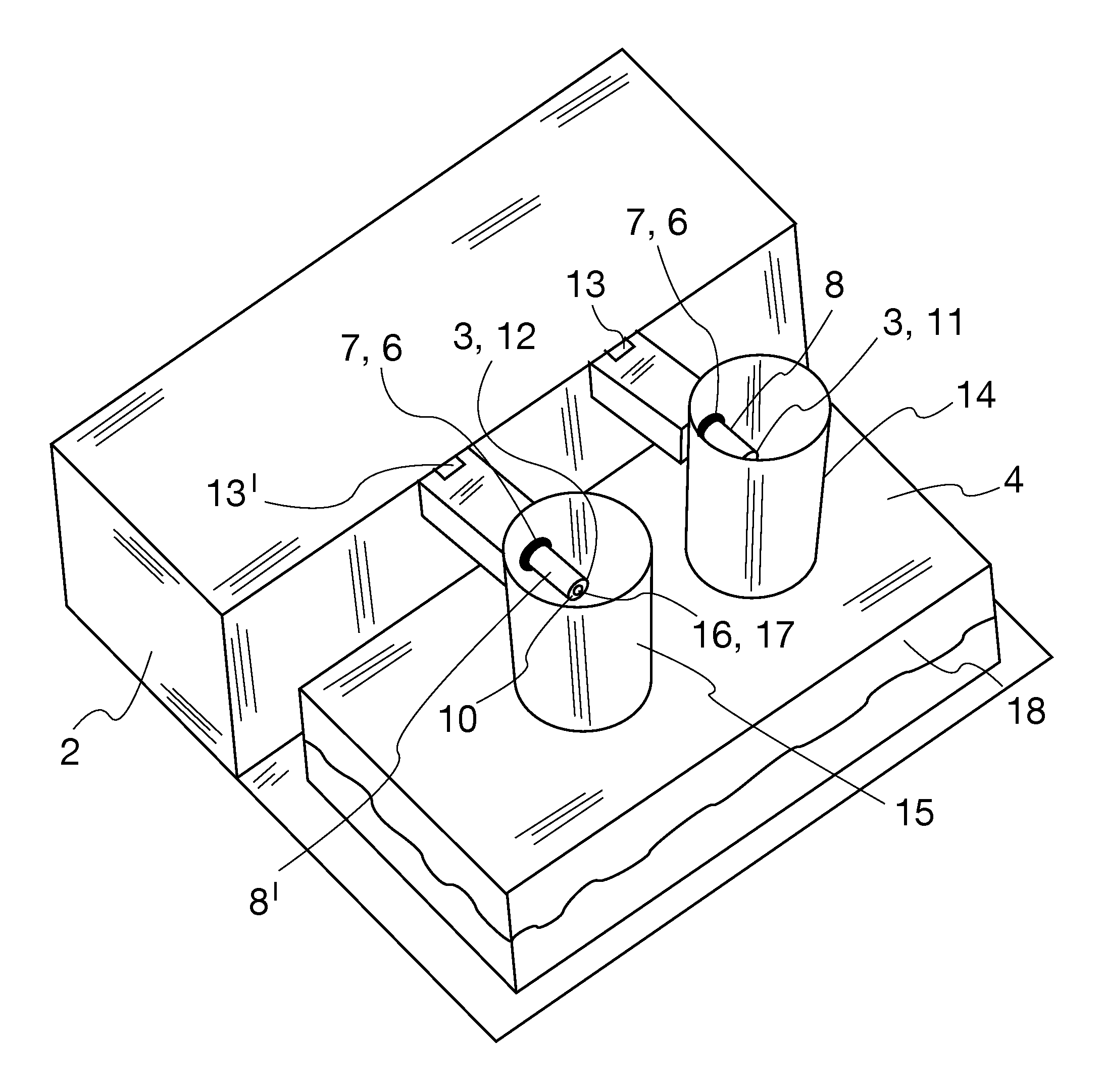
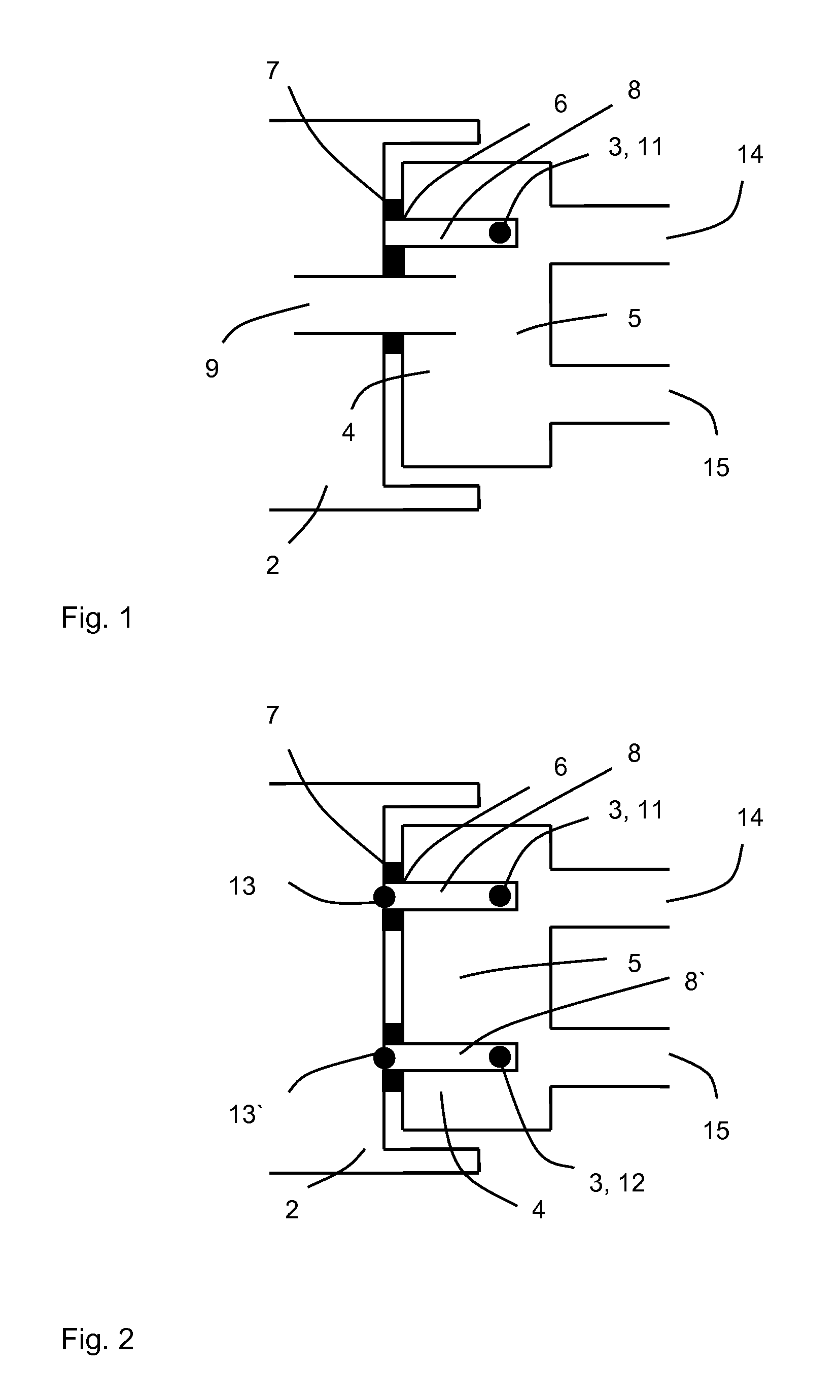
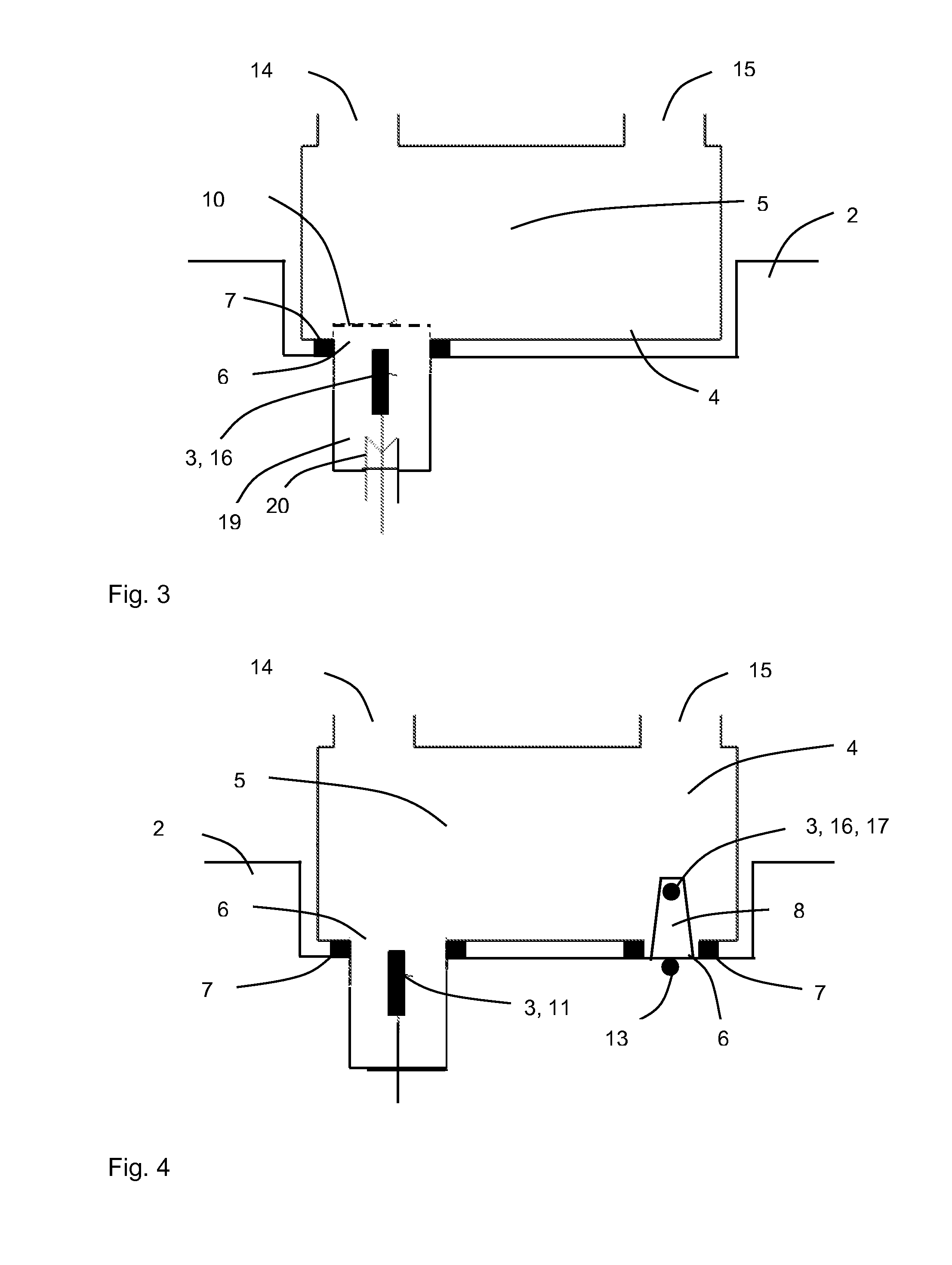
[0024]FIG. 1 shows a schematically simplified view of a mixing chamber 4 for humidifying a breathing gas to be humidified for the artificial respiration of a patient. The mixing chamber 4 has a gas-carrying area 5, a breathing gas inflow channel 14 and a breathing gas outflow channel 15, wherein a breathing gas to be humidified is fed through the breathing gas inflow channel 14 to the mixing chamber and leaves as humidified breathing gas after taking up moisture or water vapor through the breathing gas outflow channel 15 of the mixing chamber 4. In the state in which it is able to function, the mixing chamber 4 is connected to a base unit 2. The mixing chamber 4 has an opening 6 on a side facing the base unit 2. The opening 6 of the mixing chamber 4 has a sealing element 7 for sealing the gas-c...


PUM


Abstract

A respiration humidifier with a base unit (2), at least one sensor (3), which is connected to the base unit (2), and a mixing chamber (4), which is designed as a mixing chamber detachable from the base unit (2), with a gas-carrying area (5), wherein the mixing chamber (4) has at least one opening (6), through which the at least one sensor (3) is in connection with the gas-carrying area (5).

Description

CROSS REFERENCE TO RELATED APPLICATIONS[0001]This application claims the benefit of priority under 35 U.S.C. §119 of German Patent Application 10 2007 039 391.3 filed Aug. 21, 2007, the entire contents of which are incorporated herein by reference.FIELD OF THE INVENTION[0002]The present invention pertains to a respiration / ventilation humidifier having a base unit with at least one sensor, and a mixing chamber detachable from the base unit. The mixing chamber has at least one said opening through which the sensor is in connection with a gas-carrying area of the mixing chamber.BACKGROUND OF THE INVENTION[0003]Respiration humidifiers for humidifying breathing gas for patients to be artificially respirated or ventilated are known from practice. They usually have a mixing chamber, in which a gas flowing in is enriched with moisture. Parameters of the breathing gas are detected by sensors in modern respiration humidifiers for controlling the humidifier.[0004]An arrangement of a temperatur...

Claims


Application Information

Patent Timeline
IPC IPC(8): A61M16/16
CPCA61M16/16A61M16/161A61M16/109
Inventor ROSSEN, THOMASKOCH, JOCHIMRADOMSKI, KLAUS
Owner DRAGERWERK AG
Why Eureka
Try Eureka