Methods and devices for atom probe mass resolution enhancement

Inactive Publication Date: 2009-02-26
CAMECA INSTR
View PDF6 Cites 3 Cited by
  • Summary
  • Abstract
  • Description
  • Claims
  • Application Information

AI Technical Summary

Benefits of technology

[0018]In an atom probe (or some other mass spectrometer) wherein a specimen is subjected to ionizing pulses which induce field evaporation of ions from the specimen, energy compensation is performed by subjecting the evaporated ions to corrective pulses which are synchronized with the ionizing pulses. These corrective pulses have a timing and magnitude such that they reduce the velocity distribution of the evaporated ions, i.e., evaporated ions of a given mass-to-charge ratio (and thus of a given species) will not have as wide of a range of velocities as they depart the specimen. A preferred arrangement is to provide each corrective pulse from a counter electrode in response to a corresponding one of the ionizing pulses. An exemplary version of this arrangement is depicted in FIG. 3A, wherein the specimen 300 is subjected to an ionizing pulse from a first counter electrode 310, and the corrective pulse is then delivered by a second counter electrode 314. Oth

Problems solved by technology

One of the inherent limitations of atom probes is that for a given MTC ratio (i.e., for a particular ionized species), a range of TOF values can be measured.
This inherent spread in the TOF measurement limits the ability of atom probe techniques to distinguish between atomic (or molecular) species of nearly the same MTC ratio.
In other words, the peaks in the TOF histogram of two different species may overlap, making it difficult to assign a specific MTC ratio to each species, and thereby making it difficult to identify the ions that are recorded in the overlapped region.
Thus, there is a limit to the mass resolution (ionic species identification) capability of an atom probe.
This variation limits the ability to resolve species that have nearly identical MTC ratios.
In practice, it is the velocity distrib

Method used


Image

  • Methods and devices for atom probe mass resolution enhancement
  • Methods and devices for atom probe mass resolution enhancement
  • Methods and devices for atom probe mass resolution enhancement

Examples


Embodiment Construction

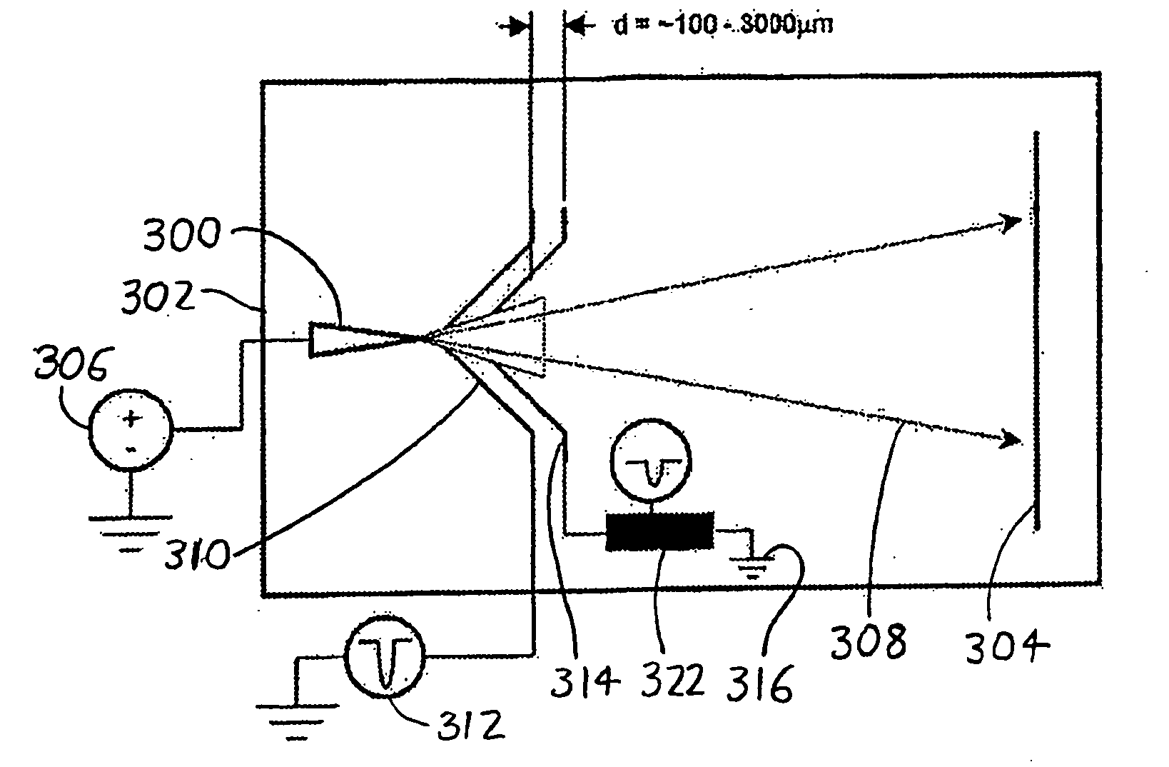
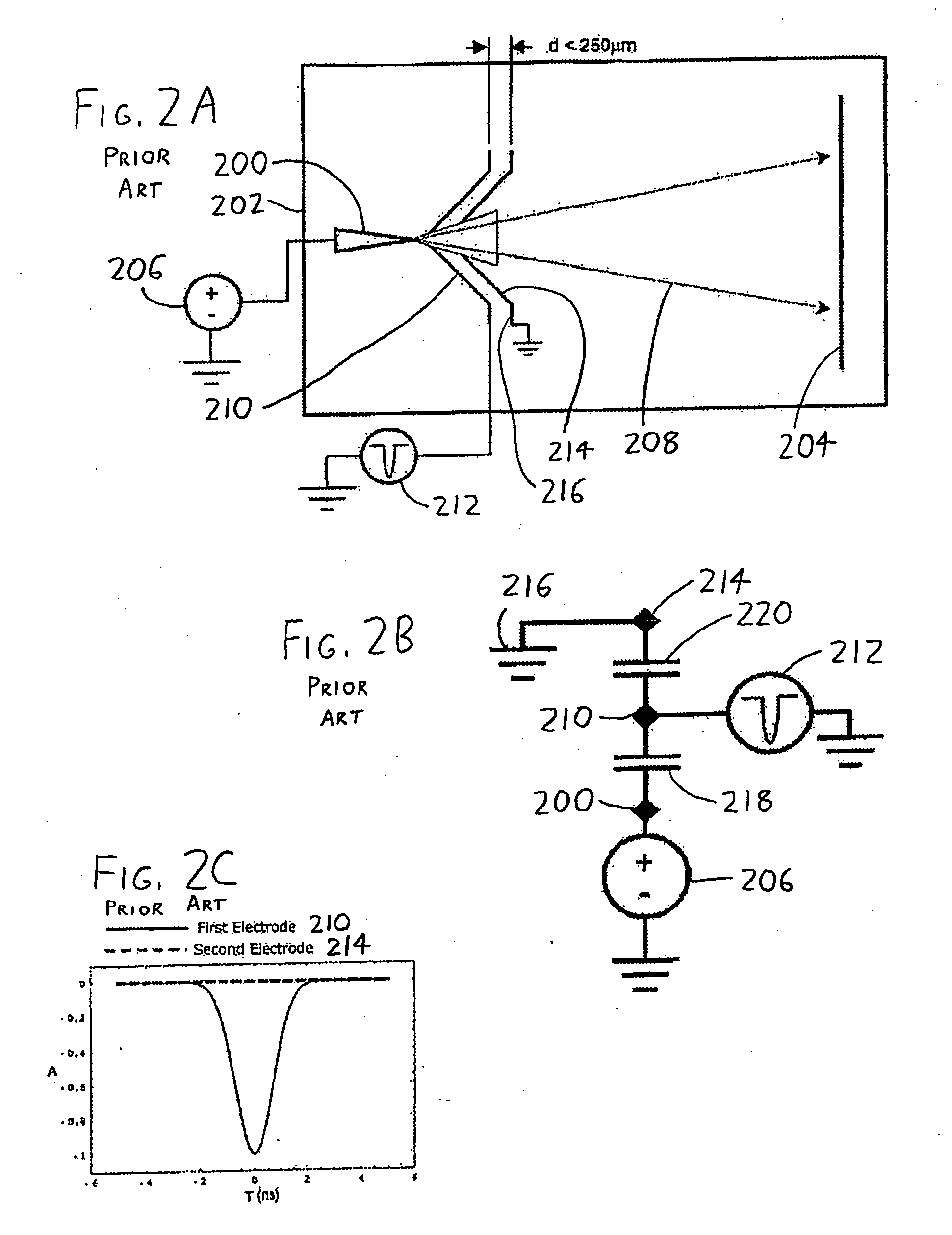
[0034]The invention provides an energy compensation arrangement for increasing the mass resolution in atom probes and other mass spectrometers which employ a pulsed ionization mechanism. Looking to the exemplary version of the invention depicted in FIG. 3A, a specimen 300 is shown in an atom probe chamber 302 spaced from a detector 304, with the specimen 300 being connected to a source 306 of standing voltage. A first counter electrode 310 is connected to an ionization pulser 312, and a second counter electrode 314 is situated adjacently to the first between the specimen 300 and detector 304, similar to the counter electrode ion deceleration arrangement discussed above and shown in FIGS. 2A-2C. However, the second counter electrode 314 also has a pulsed voltage applied to it, with the pulse being tailored to accelerate and / or decelerate the ions 308 passing it so as to reduce the variation in time of flight discussed previously with reference to FIG. 1. For example, in the preceding...


PUM


Abstract

In an atom probe or other mass spectrometer wherein a specimen is subjected to ionizing pulses (voltage pulses, thermal pulses, etc.) which induce field evaporation of ions from the specimen, the evaporated ions are then subjected to corrective pulses which are synchronized with the ionizing pulses. These corrective pulses have a magnitude and timing sufficient to reduce the velocity distribution of the evaporated ions, thereby resulting in increased mass resolution for the atom probe/mass spectrometer. In a preferred arrangement, ionizing pulses are supplied to the specimen from a first counter electrode adjacent the specimen. The corrective pulses are then supplied from a second counter electrode which is coupled to the first via a passive or active network, with the network controlling the form (timing, amplitude, and shape) of the corrective pulses.

Description

BACKGROUND OF THE INVENTION[0001]Atom probes are analytical instruments that analyze the atomic-level composition of materials by field evaporation of atoms and small molecules from a specimen, and measuring their time of flight (TOF) from the specimen to a detector some distance away. See, for example, U.S. Pat. Nos. 5,061,850, 5,440,124 and 6,576,900 to Kelly et al.; International Publications WO 99 / 14793 and WO2004 / 111604; and Kelly et al., Ultramicroscopy 62:29-42 (1996).[0002]In a typical atom probe, the specimen is in the form of a sharp tip (often having a tip radius of ˜50 nm), and is held at a semi-static standing voltage that is below that necessary to cause field evaporation of the atoms at the tip of the specimen. A counter electrode, which usually has an aperture therein, is spaced about or at a slight distance from the specimen tip, with the specimen tip pointing through the aperture. A pulsed (usually negative) voltage is applied to the counter electrode, and / or a pul...

Claims


Application Information

Patent Timeline
IPC IPC(8): B01D59/44
CPCH01J49/168
Inventor GRIBB, TYEOLSON, JESSE D.LENZ, DANIEL R.BUNTON, JOSEPH H.
Owner CAMECA INSTR
Why Eureka
Try Eureka