Pipe welding holding device and method for holding pipes with flanges in place during welding to vessel walls and other structures

Inactive Publication Date: 2009-02-26
BARNES JR ROBBIE DEAN
View PDF4 Cites 17 Cited by
  • Summary
  • Abstract
  • Description
  • Claims
  • Application Information

AI Technical Summary

Benefits of technology

[0017]The apparatus of the present invention enables one person—the welder—to more accurately set the nozzle and flange by providing an adjustable holder for the nozzle and flange attached to the wall of the vessel or tank using magnets that may be act

Problems solved by technology

This process frequently results in inaccurate welds, which must be broken or cut and re-welded two, three, or four times before an acceptable, albeit frequently not perfectly accurate, weld has been obtained.
Frequently even after an acceptable weld is achieved, when a nozzle or pipe with a corresponding flange is connected with the nozzle and flange that has been welded to the tank wall, the holes do not line up to the ideal level of accuracy and the bolts and the nozzle and flange must be slightly twisted to fit the connecting nozzle and flange; this can result in long-term damage to the nozzle because of the stress to the twisted pipe, and to the bolts connecting the flanges.
Sometimes the welding team finds it necessary to drive the bolts holding the flanges in place with a hammer, which damages the threads of the bolts and thereby weakens them and m

Method used


Image

  • Pipe welding holding device and method for holding pipes with flanges in place during welding to vessel walls and other structures
  • Pipe welding holding device and method for holding pipes with flanges in place during welding to vessel walls and other structures
  • Pipe welding holding device and method for holding pipes with flanges in place during welding to vessel walls and other structures

Examples


Embodiment Construction

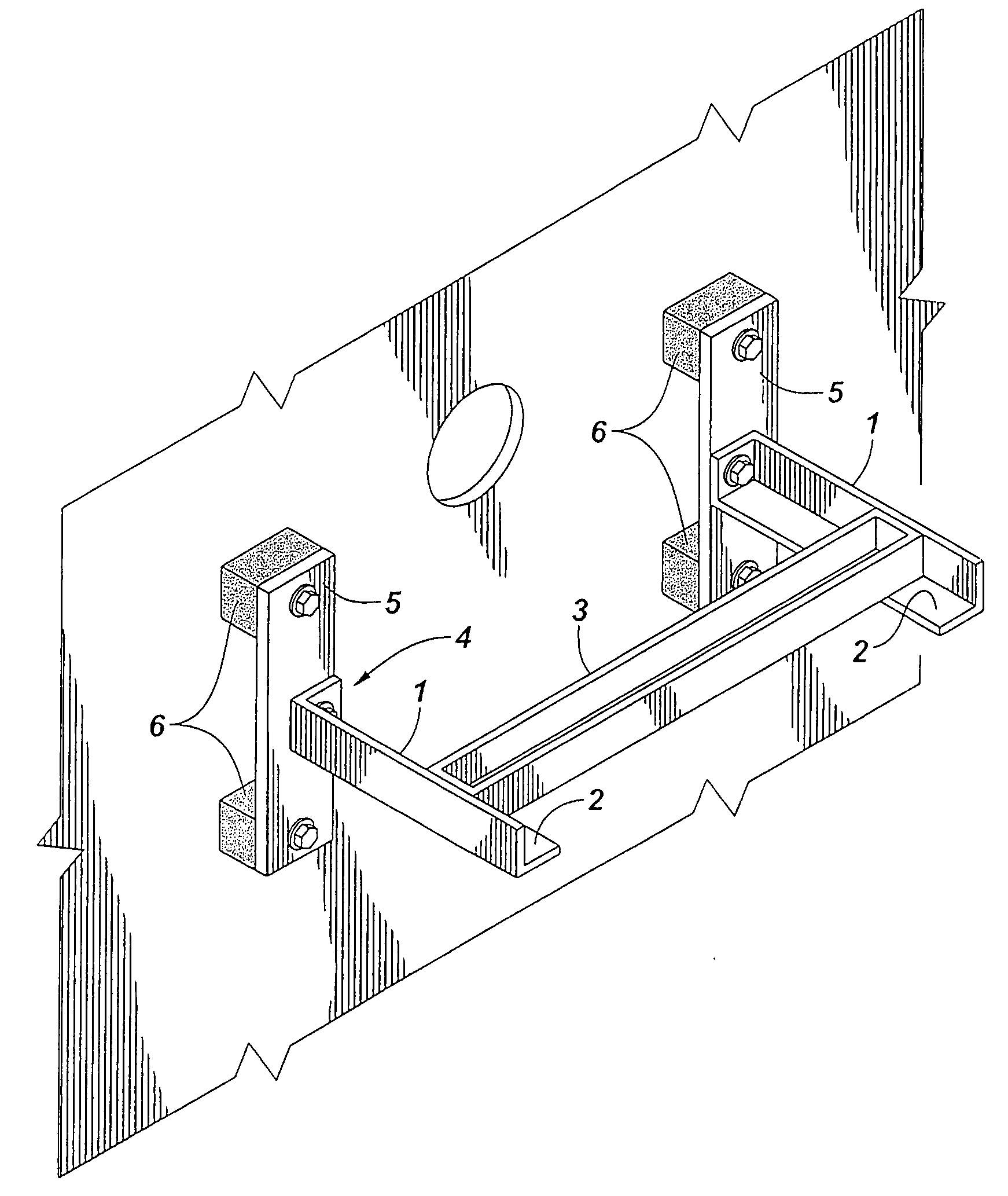
[0024]The present invention now will be described more fully hereinafter with reference to the accompanying drawings in which a preferred embodiment of the invention is shown. This invention, however, may be embodied in many different forms and should not be construed as limited to the embodiment set forth herein; rather, this embodiment is provided so that this disclosure will be thorough and complete, and will fully convey the scope of the invention to those skilled in the art. (Like numbers refer to like elements throughout.)

[0025]The invention is a device to hold the flange and pipe or nozzle in place during the welding process. The invention can be set in place easily by one person. It also is simple in design and easy to assemble and disassemble to move to a new location for other welding work. The invention consists of the following:

[0026]The basic device, FIG. 1, consists of a frame to hold a pipe or nozzle with flange or similar device using two angle pieces (1) hereinafter...


PUM


Abstract

A pipe welding holding device and a method for holding pipes with flanges in place during welding to vessel walls and other structures. The invention provides an easy-to-use mechanical device, and a method, to hold the flange connected to a pipe in place during welding and enables the welder to accurately and reliably set the flange and pipe so that much fewer errors are made in welding than at present, and a method for using said device.

Description

RELATED APPLICATIONS[0001]NoneCOPYRIGHT STATEMENT[0002]A portion of the disclosure of this patent document contains material which is subject to copyright protection. The copyright owner has no objection to the facsimile reproduction by anyone of the patent document or the patent disclosure, as it appears in the Happened and Trademark office patent file or records, but otherwise reserves all copyright rights whatsoever.BACKGROUND OF THE INVENTION[0003]1. Field of the Invention[0004]The present invention relates to a device and method for holding nozzles and pipes, and other similar material, in place while being welded to tanks and other vessels in chemical plants and refineries, oil refineries, oil field plants, barges, ships, heating boilers, some railroad cars, nuclear power plants, electrical power plants, water purification plants, sewer plants, off-shore rigs, and other similar facilities.[0005]2. Background of the Invention[0006]In chemical plants and refineries, oil refineri...

Claims


Application Information

Patent Timeline
IPC IPC(8): B23K37/04B23K37/053B25B11/02
CPCB23K37/0533B25B11/02B23K2201/06B23K2101/06
Inventor BARNES, JR., ROBBIE DEAN
Owner BARNES JR ROBBIE DEAN
Why Eureka
Try Eureka