Compact two-element infrared objective lens and IR or thermal sight for weapon having viewing optics

a two-element, infrared objective technology, applied in the field of relativly compact imaging lens arrangement of infrared optical system, can solve the problems of difficult design to achieve diffraction-limited performance, prior art lens design is not particularly suitable for use with thermal or ir sights for small arms

Inactive Publication Date: 2009-02-26
THE BF GOODRICH CO
View PDF18 Cites 30 Cited by
  • Summary
  • Abstract
  • Description
  • Claims
  • Application Information

AI Technical Summary

Benefits of technology

[0009]The invention can further take the form of a long-wave infrared sight for weapon such as a small arms. The sight includes a detector for detecting infrared radiation (e.g., IR-sensitive photodiode array, un-cooled microbolometer array, or other device) and an objective lens in accordance wit

Problems solved by technology

Many of the prior art lens designs are not particularly suitable for use with thermal or IR sights for small arms, and particularly arms such as rifles carried by a soldier, because they incorporate a relatively large number of lens elements in the design and therefore re

Method used


Image

  • Compact two-element infrared objective lens and IR or thermal sight for weapon having viewing optics
  • Compact two-element infrared objective lens and IR or thermal sight for weapon having viewing optics
  • Compact two-element infrared objective lens and IR or thermal sight for weapon having viewing optics

Examples


example 1

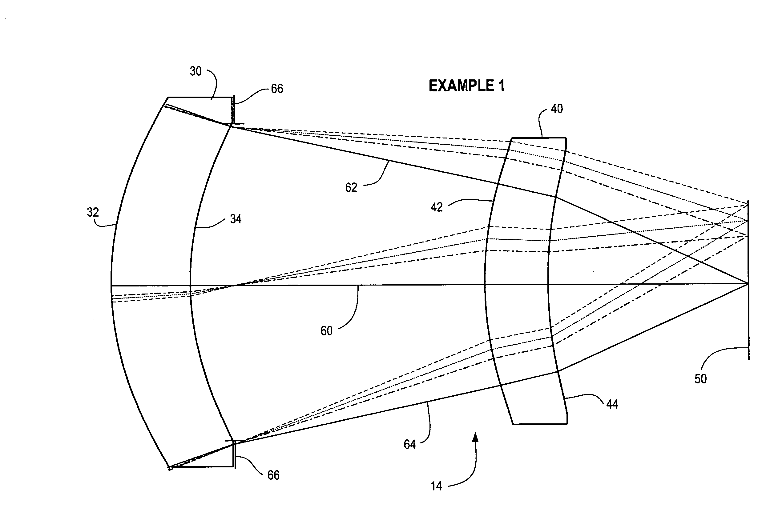
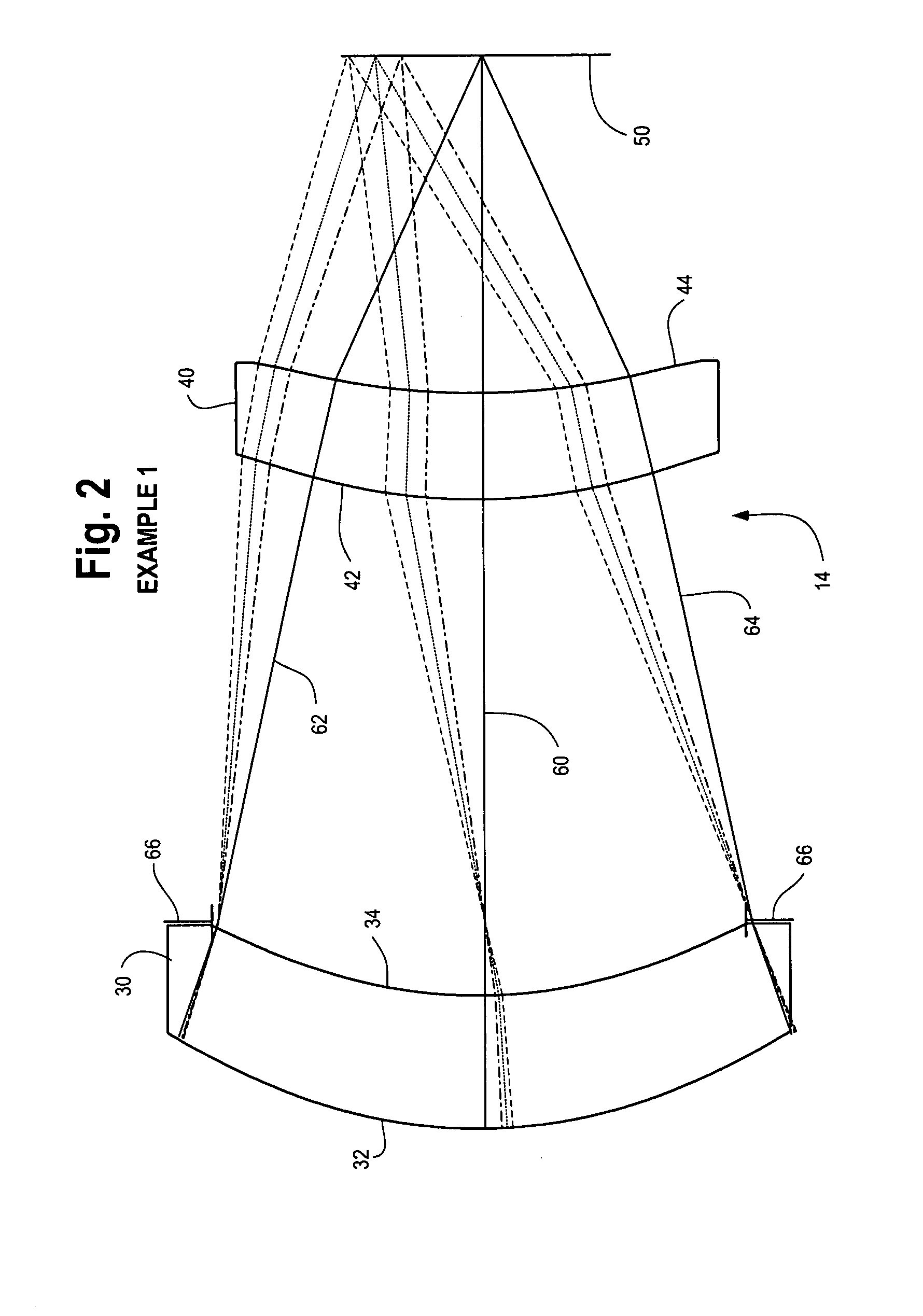
28.3 mm Focal Length, F1.1 Two Element IR Objective Lens (FIG. 2)

[0026]FIG. 2 is an illustration of a lens design in accordance with a first embodiment. The design is optimized to operate in the long-wave infrared (LWIR) band of the electromagnetic spectrum. The design features two lens elements 30 and 40. Front surface 32 of the first lens element 30 is convex and receives incident radiation from the scene. Rear surface 34 is concave. The front surface 42 of the second lens element 40 is convex and the rear surface 44 is concave. Surfaces 32, 34, 42 and 44 are aspherical. The details of the prescription of the lenses are set forth in the Appendix A. The lens elements 30 and 40 are made from germanium in the illustrated embodiment. The lens elements direct radiation onto the focal plane 50. A thermal or IR detection device (not shown) is placed at the focal plane 50.

[0027]The design has a 28.3 mm focal length, an f-number of 1.1, and a field angle of ±11.2 degrees (total field-of-vi...

example 2

50.3 mm F1.4 Two Element IR Objective Lens (FIG. 10)

[0037]FIG. 10 is an illustration of a lens 14 in accordance with a second embodiment. The lens is designed to operate in the long-wavelength infrared. The lens features a first lens element 30 with front and rear surfaces 32 and 34, and a second lens element 40 having front and rear surfaces 42 and 44, respectively, which direct incident light from a scene and form an image on a focal plane 50. Surfaces 32 and 42 are convex and surfaces 34 and 44 are concave. A detection device (not shown) for detecting radiation in the IR portion of the spectrum is located at the focal plane 50. An aperture stop 66 is placed between the first and second lens elements 30 and 40.

[0038]Lens surfaces 34, 42 and 44 are aspherical. Lens surface 32 is spherical. The prescription for the lens elements 30 and 40 are given in Appendix B. The lens elements are constructed from germanium.

[0039]The design has a 50.3 mm focal length, f-number of 1.4, and a fiel...

example 3

101.4 mm F1.4 Two Element LWIR Objective Lens (FIG. 18)

[0043]FIG. 18 is an illustration of a lens design 14 in accordance with a third embodiment. The lens 14 features a first lens element 30 and a second lens element 40 which together form an image on a focal plane 50. Surface 32 of lens element 30 is convex relative to the focal plane 50; surface 34 of lens element 30 is concave relative to the focal plane 50. Surface 42 of lens element 40 is concave, as is lens surface 44. Surface 32 is spherical and surfaces 34, 42 and 44 are aspherical. The prescription of the lens 14 is given in Appendix C. The lens is designed to operate in the long-wave infrared. Accordingly, the lens elements 30 and 40 are constructed from a material selected to pass radiation in this band. In this example lens element 30 is made from germanium and lens element 40 is made from zinc sulfide.

[0044]An aperture stop 66 is placed adjacent to the lens element 30 between the first and second lens elements 30 and 4...


PUM


Abstract

A compact objective lens is disclosed which is particularly suitable for infrared optical systems. The lens features a simple design with only two lens elements, namely a first lens element receiving incident radiation and having front and rear surfaces, and a second lens element receiving incident radiation from the first element and having front and rear surfaces. The lens forms an image of a scene on a focal plane. At least three of the four surfaces of the elements are aspheric surfaces. The lens has an f-number less than about 2, a field-of-view less than about 30 degrees, and an effective focal length less than about 6 inches. The elements are made from a material selected to pass radiation in the infrared band of the electromagnetic spectrum, e.g., germanium. The lens is suitable for use as an objective lens for a long-wave infrared sight for small arms, e.g., rifle or shoulder-launched surface to air missile launching system, i.e., a lens optimized for operating in the electromagnetic spectrum between about 7.5 and about 15 micrometers.

Description

BACKGROUND OF THE INVENTION[0001]This invention is related to the field of infrared (IR) optical systems. More particularly, this invention relates to a relatively compact imaging lens arrangement for an infrared optical system featuring two lens elements, a low f-number and diffraction-limited performance. The lens system is particularly suitable for incorporation into an infrared or thermal weapon sight.[0002]Cameras, weapon sights, and other types of optical systems typically incorporate an imaging lens arrangement having a group of lenses which collect light from a scene and direct such light onto a detector placed at focal plane of the optical system. A variety of lens designs are known in the art. Representative examples are disclosed in the following U.S. Patents: Chen et al., U.S. Pat. No. 7,024,656; Canzek, U.S. Pat. No. 4,738,496; Grey, U.S. Pat. No. 3,784,287; Cooper, U.S. Pat. No. 4,999,005; Ohno, U.S. Pat. Nos. 5,067,803 and 5,835,281; Ruben, U.S. Pat. No. 3,944,337; Ch...

Claims


Application Information

Patent Timeline
IPC IPC(8): G02B13/14
CPCG02B9/04G02B13/18G02B13/14
Inventor BAKER, ALLIE M.
Owner THE BF GOODRICH CO
Why Eureka
Try Eureka