Thermally assisted magnetic head, head gimbal assembly, and hard disk drive

a technology of magnetic head and head gimbal, which is applied in the direction of combination recording, data recording, instruments, etc., can solve the problems of difficult electric connection between electromagnetic transducer or magnetic reading device, and achieve the effect of favorable yield

Active Publication Date: 2009-02-26
TDK CORPARATION
View PDF18 Cites 54 Cited by
  • Summary
  • Abstract
  • Description
  • Claims
  • Application Information

AI Technical Summary

Benefits of technology

[0020]The present invention can provide a thermally assisted magnetic head with a favorable yield, ...

Problems solved by technology

In such a mode, electric connection is hard to achieve between an electromagnetic transducer or magnetic reading device in the slider and an electrode provided in a susp...

Method used


Image

  • Thermally assisted magnetic head, head gimbal assembly, and hard disk drive
  • Thermally assisted magnetic head, head gimbal assembly, and hard disk drive
  • Thermally assisted magnetic head, head gimbal assembly, and hard disk drive

Examples


first embodiment

[0030]Hard Disk Drive

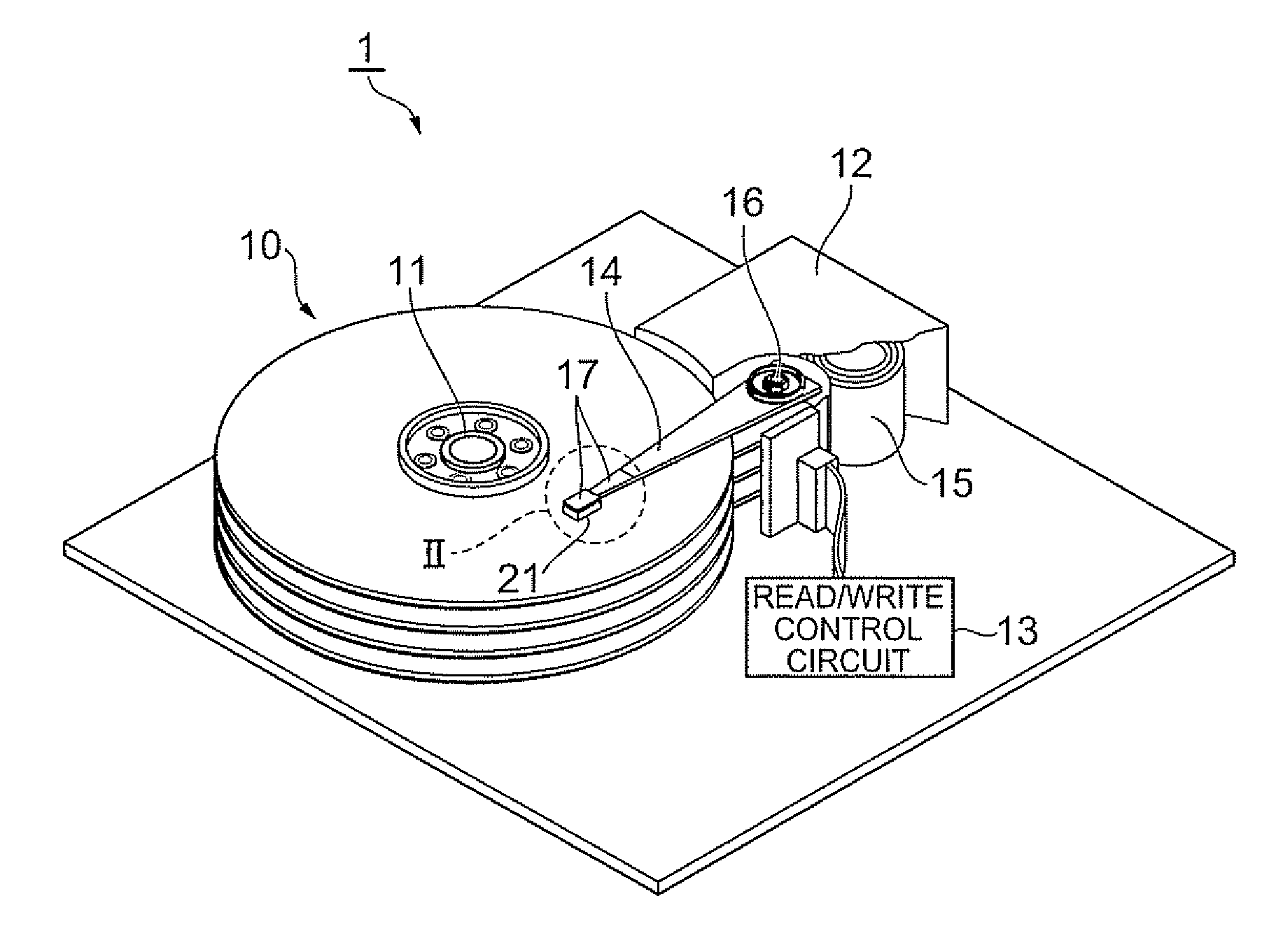
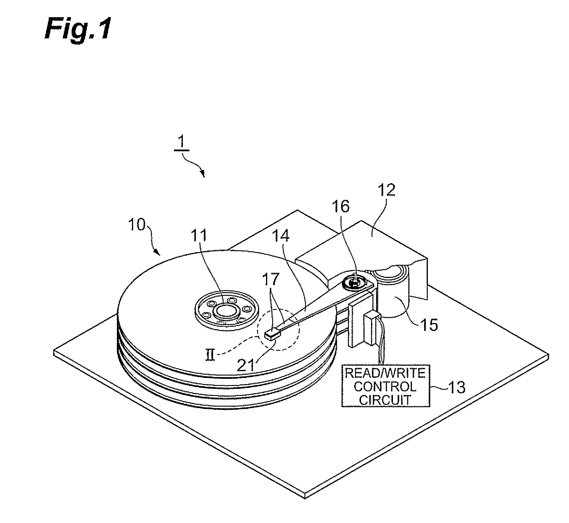
[0031]FIG. 1 is a perspective view of the hard disk drive in accordance with an embodiment.

[0032]The hard disk drive 1 comprises a plurality of magnetic disks 10 which are magnetic recording media rotating about a rotary shaft of a spindle motor 11, an assembly carriage apparatus 12 for positioning thermally assisted magnetic heads 21 onto tracks, and a read / write control circuit 13 for controlling writing and reading actions by the thermally assisted magnetic heads 21 and regulating a laser diode 40 which is a light source for generating laser light for thermally assisted magnetic recording as will be explained later in detail.

[0033]The assembly carriage apparatus 12 is provided with a plurality of driving arms 14. These driving arms 14 can be swung about a pivot bearing shaft 16 by a voice coil motor (VCM) 15, and are laminated in a direction along the pivot bearing shaft 16. A head gimbal assembly (HGA) 17 is attached to a leading end part of each driving arm...

second embodiment

[0113]The second embodiment of the present invention will now be explained with reference to FIG. 8. The second embodiment is the same as the first embodiment except for the outermost device electrodes 371, 374 in the track width direction of the slider 22, which will solely be explained.

[0114]In this embodiment, the device electrodes 371, 374 are also exposed at surfaces 38b, 38c in the track width direction of the slider 22, i.e., side faces of the medium-opposing surface S, respectively. In the end parts 471a, 474a on the slider side of the leads 471, 474, the surfaces opposing the slider are also exposed, while the slider-opposing surfaces of the end parts 471a, 474a of the leads 471, 474 are electrically connected to side faces of the device electrodes 371, 374 by reflow solder pieces 250, respectively. This embodiment can also reduce bonding wires.

[0115]The present invention can be modified in various ways without being restricted to the above-mentioned embodiments

[0116]For ex...


PUM


Abstract

A slider has a slider substrate, an electromagnetic transducer, a waveguide for receiving light from a surface on the side opposite from a medium-opposing surface and guiding the light to the medium-opposing surface side, and a device electrode electrically connected to the electromagnetic transducer. A light source unit includes a light source supporting substrate, a light source, and a lead extending from the slider side to the side opposite from the slider and having both end parts exposed at a surface of the light source unit. The device electrode of the slider is exposed at the surface of the slider on the side opposite from the medium-opposing surface without being covered with the light source unit. An end part on the slider side of the lead of the light source unit is soldered to the device electrode of the slider.

Description

BACKGROUND OF THE INVENTION[0001]1. Field of the Invention[0002]The present invention relates to a thermally assisted magnetic head which writes signals by a thermally assisted magnetic recording scheme, a head gimbal assembly (HGA) equipped with the thermally assisted magnetic head, and a hard disk drive equipped with the HGA.[0003]2. Related Background Art[0004]As hard disk drives have been increasing their recording density, thin-film magnetic heads have been required to further improve their performances. As the thin-film magnetic heads, those of composite type having a structure in which a magnetism detecting device such as magnetoresistive (MR) device and an electromagnetic transducer such as electromagnetic coil device are laminated have been in wide use, while these devices read / write data signals from / onto magnetic disks which are magnetic recording media.[0005]In general, a magnetic recording medium is a sort of discontinuous body in which magnetic fine particles are assem...

Claims


Application Information

Patent Timeline
IPC IPC(8): G11B5/02G11B5/48
CPCG11B5/02G11B2005/0021G11B2005/0005G11B5/314G11B5/6088
Inventor TANAKA, KOSUKESHIMAZAWA, KOJIITO, YASUHIRO
Owner TDK CORPARATION
Why Eureka
Try Eureka