Method and apparatus for basis material decomposition with k-edge materials

a technology of k-edge materials and decomposition methods, applied in the field of diagnostic imaging, can solve the problems of large error, non-negligible error, and small error due to incorrect application of basis material assumption, and achieve the effect of increasing the accuracy of decomposition of energy dependent projection data

Inactive Publication Date: 2009-02-26
GENERAL ELECTRIC CO
View PDF12 Cites 50 Cited by
  • Summary
  • Abstract
  • Description
  • Claims
  • Application Information

AI Technical Summary

Benefits of technology

[0012]Therefore, it would be desirable to design an apparatus and method that increase a...

Problems solved by technology

Practically, however, many dual energy systems are designed with very broad energy spectra.
The error due to the incorrect application of the basis material assumption is very small when these broad energy spectra are ...

Method used


Image

  • Method and apparatus for basis material decomposition with k-edge materials
  • Method and apparatus for basis material decomposition with k-edge materials
  • Method and apparatus for basis material decomposition with k-edge materials

Examples


Embodiment Construction

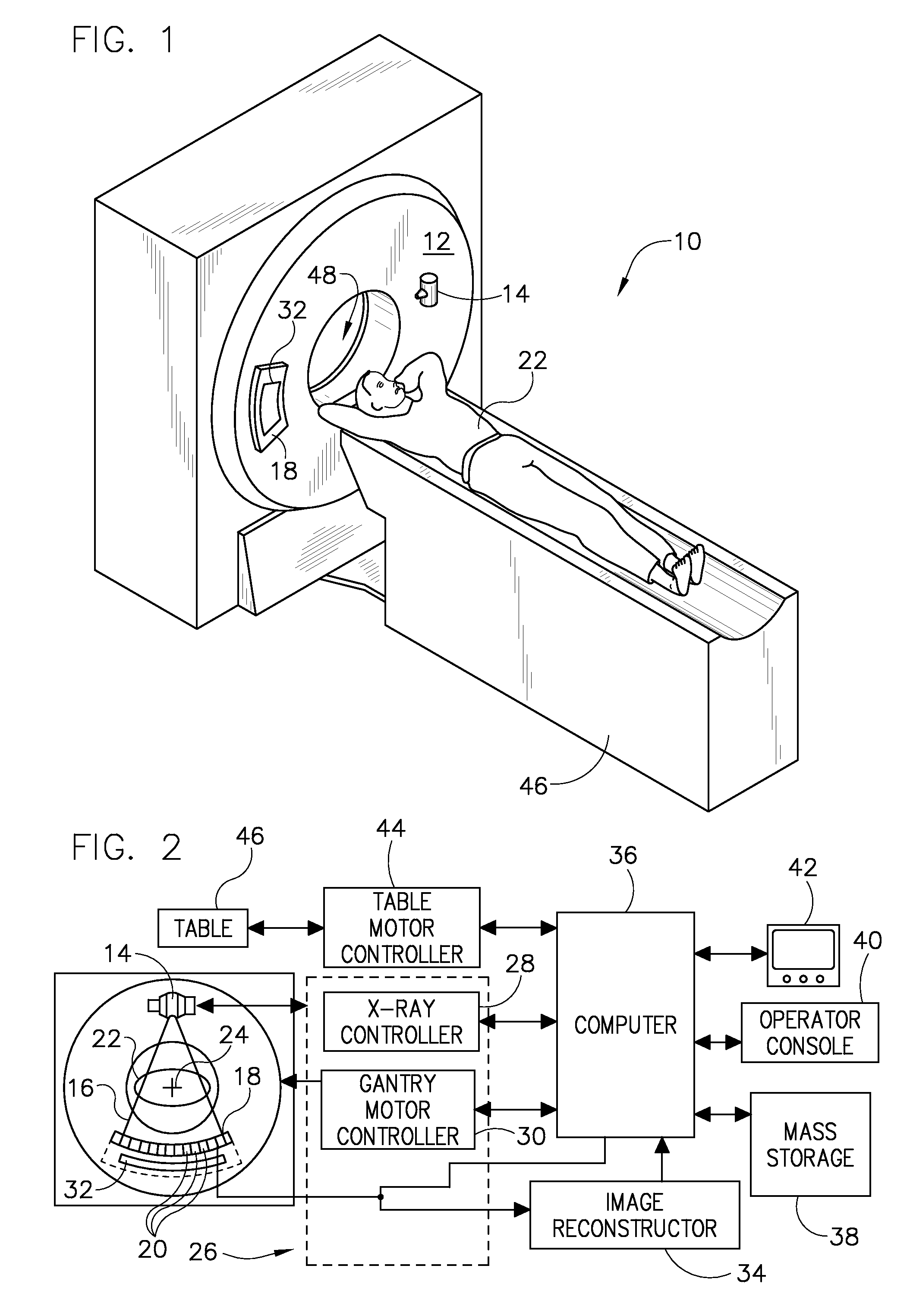
[0027]Exemplary diagnostics devices comprise x-ray systems, magnetic resonance (MR) systems, ultrasound systems, computed tomography (CT) systems, positron emission tomography (PET) systems, and other types of imaging systems. Exemplary applications of x-ray sources comprise imaging, medical, security, and industrial inspection applications. The operating environment of the present invention is described with respect to a sixty-four-slice computed tomography (CT) system. However, it will be appreciated by those skilled in the art that the present invention is equally applicable for use with other multi-slice configurations. Moreover, the present invention will be described with respect to the detection and conversion of x-rays. However, one skilled in the art will further appreciate that the present invention is equally applicable for the detection and conversion of other high frequency electromagnetic energy. The present invention will be described with respect to a “third generati...


PUM


Abstract

A diagnostic imaging system includes a high frequency electromagnetic energy source that emits a beam of high frequency electromagnetic energy toward an object to be imaged, a detector that receives high frequency electromagnetic energy emitted by the high frequency electromagnetic energy source, and a data acquisition system (DAS) operably connected to the detector. A computer is operably connected to the DAS and is programmed to generate corresponding sets of projection values for three or more energy spectra through employment of attenuation coefficients of three or more basis materials to simulate responses of the diagnostic imaging system to a plurality of lengths of the three or more basis materials wherein the three or more basis materials comprise two or more non K-edge basis materials and one or more K-edge basis materials.

Description

BACKGROUND OF THE INVENTION[0001]The present invention relates generally to diagnostic imaging and, more particularly, to a method and apparatus of computed tomography imaging systems and basis material decomposition within such systems.[0002]Exemplary diagnostics devices comprise x-ray systems, magnetic resonance (MR) systems, ultrasound systems, computed tomography (CT) systems, positron emission tomography (PET) systems, and other types of imaging systems. Typically, in CT imaging systems, an x-ray source emits a fan-shaped beam toward a subject or object, such as a patient or a piece of luggage. Hereinafter, the terms “subject” and “object” shall include anything capable of being imaged. The beam, after being attenuated by the subject, impinges upon an array of radiation detectors. The intensity of the attenuated beam radiation received at the detector array is typically dependent upon the attenuation of the x-ray beam by the subject. Each detector element of the detector array ...

Claims


Application Information

Patent Timeline
IPC IPC(8): G01N23/06
CPCA61B5/4869A61B6/032A61B6/4035A61B6/4042G01N2223/424A61B6/4241A61B6/482G01N23/087G01N2223/423A61B6/405
Inventor WALTER, DEBORAH JOYWU, XIAOYETKACZYK, JOHN ERICDU, YANFENG
Owner GENERAL ELECTRIC CO
Why Eureka
Try Eureka