Fuel cell stack and method for making the same
a fuel cell and stack technology, applied in the direction of cell components, final product manufacturing, sustainable manufacturing/processing, etc., can solve the problems of power-generating performance degraded and electrical conductivity between separators and current collectors may be reduced, and achieve the effect of enhancing the power-generating performance of the fuel cell stack and reducing the penetration electrical resistance between the separator and the current collector
- Summary
- Abstract
- Description
- Claims
- Application Information
AI Technical Summary
Benefits of technology
Problems solved by technology
Method used
Image
Examples
example 1
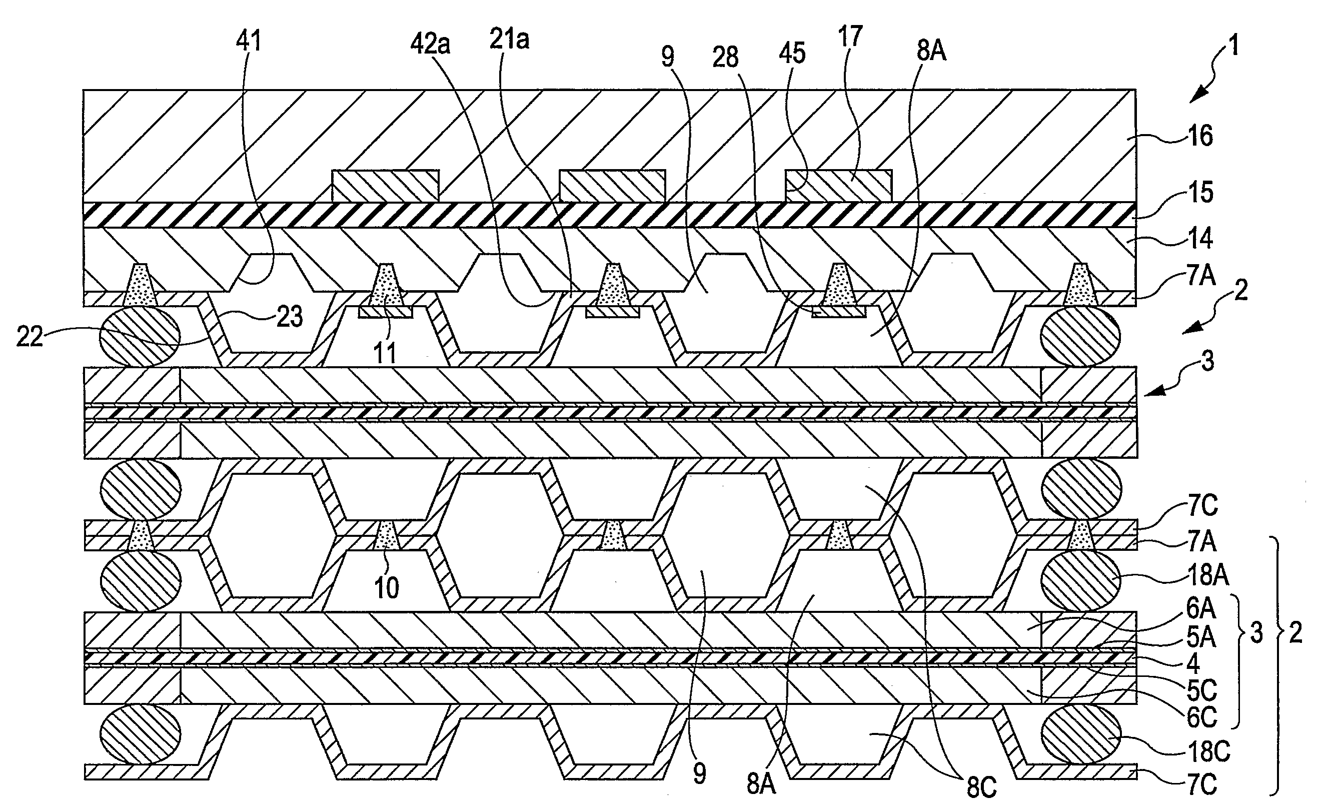
[0089]Example 1 is shown in FIG. 7. In Example 1, the first separator 7A and the second separator 7C each have line-shaped welding parts 35 and dot-shaped welding parts 36 appropriately disposed according to the size of the projections 21 and 22, warpage shapes after pressing, and the like.
[0090]When the gas channel 8A and the gas channel 8C, respectively defined by the first separator 7A and the second separator 7C, and the temperature-controlling medium channel 9 extend in straight lines, the projections 21 are in close contact with the current collector 14. When these channels have serpentine shapes, it is possible that a gap will be generated between the projection 21 and the current collector 14. The line-shaped welding parts 35 and the dot-shaped welt spots 36 are appropriately combined and disposed according to the state of distribution of the contact portions of the first separator 7A and the second separator 7C.
[0091]The ratio of the area of welding (welded area) of the wel...
example 2
[0095]In Example 2, the welding parts 11 for the first and second separators 7A and 7C and the current collectors 14 are distributed such that the density of the welding parts 11 is high in positions where the current density is relatively high between the current collector 14 and each of the first separator 7A and the second separator 7C.
[0096]FIG. 10 is a schematic structural diagram of the membrane electrode assembly 3. Referring to FIG. 10, the membrane electrode assembly 3 includes an inlet manifold 59 for the gas channel 8A, an outlet manifold 60 for the gas channel 8A, an inlet manifold 61 for the gas channel 8C, an outlet manifold 62 for the gas channel 8C, an inlet manifold 63 for the temperature-controlling medium channel 9, an outlet manifold 64 for the temperature-controlling medium channel 9, and a gasket 65.
[0097]The current density in a central part 57A in a reaction surface 57 of the membrane electrode assembly 3 is higher than that in a peripheral part 57B. Thus, in...
example 3
[0099]Example 3 is shown in FIG. 11. As shown in FIG. 11, the current collector 14 of this example has bossed parts 67 for retrieving electric power. The distribution density of the welding parts 11 for welding the current collectors 14 to the first separator 7A and the second separator 7C is controlled to be higher in regions 57C of the reaction surface 57 opposing the bossed parts 67 than in other regions.
[0100]The bossed parts 67 project from the surface of the current collector 14 and penetrate the end plate 16 so that the electromotive force of the fuel cell stack 1 can be derived from the bossed parts 67.
[0101]In this manner, by increasing the electrical conductivity between the current collector 14 and each of the first separator 7A and the second separator 7C so as to correspond to the state in which the current density distribution of the reaction surface 57 of the membrane electrode assembly 3 is high in the regions 57C opposing the bossed parts 67, the electromotive force...
PUM
| Property | Measurement | Unit |
|---|---|---|
| Fraction | aaaaa | aaaaa |
| Temperature | aaaaa | aaaaa |
| Electrical resistance | aaaaa | aaaaa |
Abstract
Description
Claims
Application Information
 - R&D
- Intellectual Property
- Life Sciences
- Materials
- Tech Scout
- Unparalleled Data Quality
- Higher Quality Content
- 60% Fewer Hallucinations
Browse by: Latest US Patents, China's latest patents, Technical Efficacy Thesaurus, Application Domain, Technology Topic, Popular Technical Reports.
© 2025 PatSnap. All rights reserved.Legal|Privacy policy|Modern Slavery Act Transparency Statement|Sitemap|About US| Contact US: help@patsnap.com


