
Machine, engine system and operating method

a technology of engine system and operating method, which is applied in the direction of engines, machines/engines, mechanical apparatus, etc., can solve the problems of difficulty in a standard turbocharger, and achieve the effect of reducing the difficulty of a standard turbocharger

Inactive Publication Date: 2009-03-05
CATERPILLAR INC
View PDF10 Cites 20 Cited by
  • Summary
  • Abstract
  • Description
  • Claims
  • Application Information

AI Technical Summary

Benefits of technology

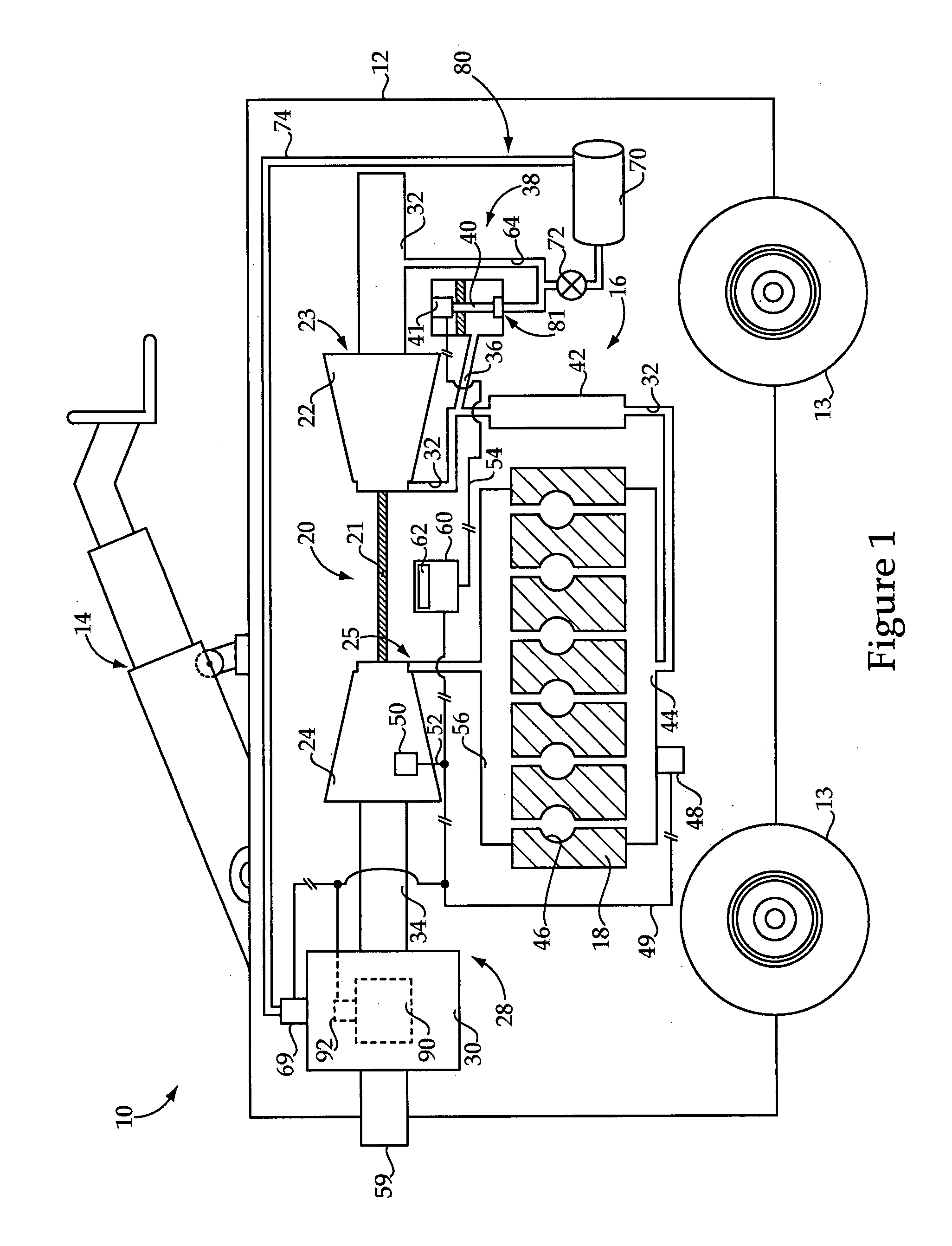
[0006]In one aspect, the present disclosure provides an engine system having an engine with an exhaust system coupled therewith. The engine system further includes a compressor configured to supply intake air to the engine, and a flow restriction device disposed in the exhaust system, the flow restriction device having a first configuration with a relatively larger flow area and a second configuration with a relatively smaller flow area. The engine system further includes a compressed air subsystem having an inlet, and a pressure control device configured to selectively fluidly connect the inlet of the compressed air subsystem with the compressor when the flow restriction device is in the second configuration.
[0007]In another aspect, the present disclosure provides a machine that includes a frame and an engine system mounted to the frame, the engine system including an engine, an exhaust system and a compressor configured to supply intake air to the engine. The engine system further includes a flow restriction device disposed in the exhaust system and having a first configuration with a relatively larger flow area, and a second configuration with a relatively smaller flow area. The machine still further includes a compressed air subsystem having an inlet, and a pressure control device configured to selectively fluidly connect the inlet of the compressed air subsystem with the compressor when the flow restriction device is in the second configuration.
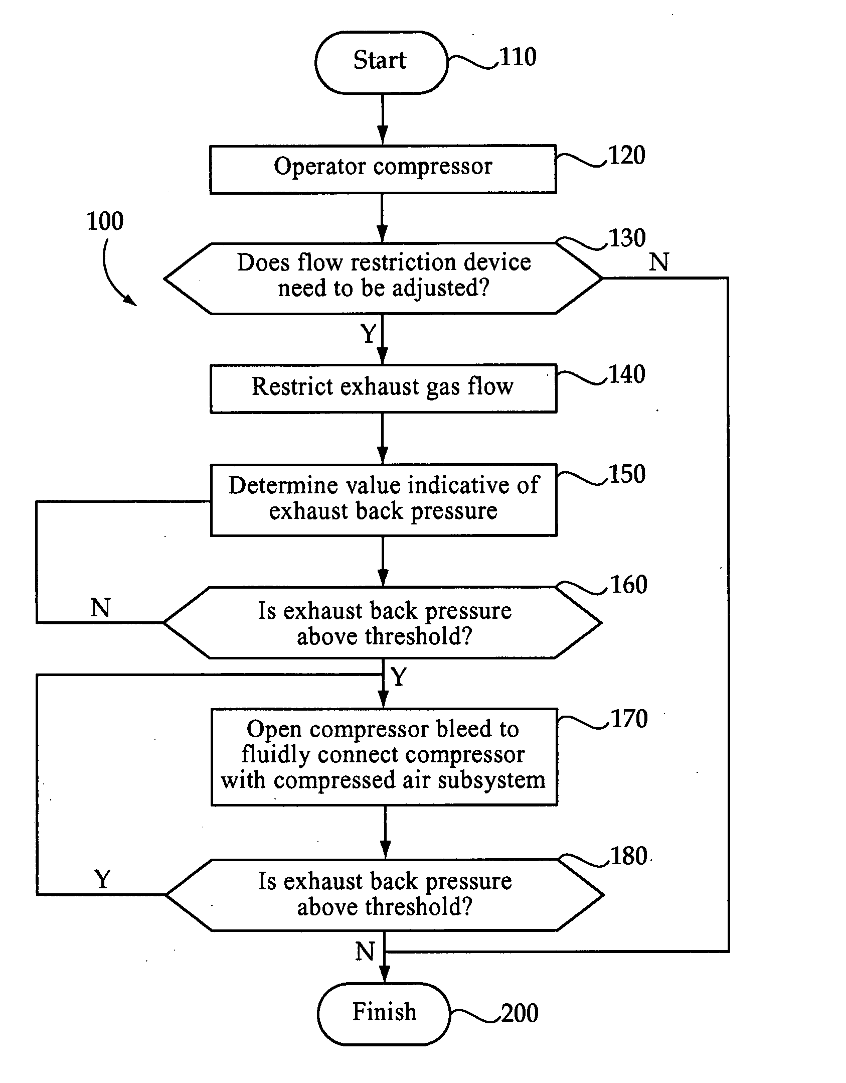
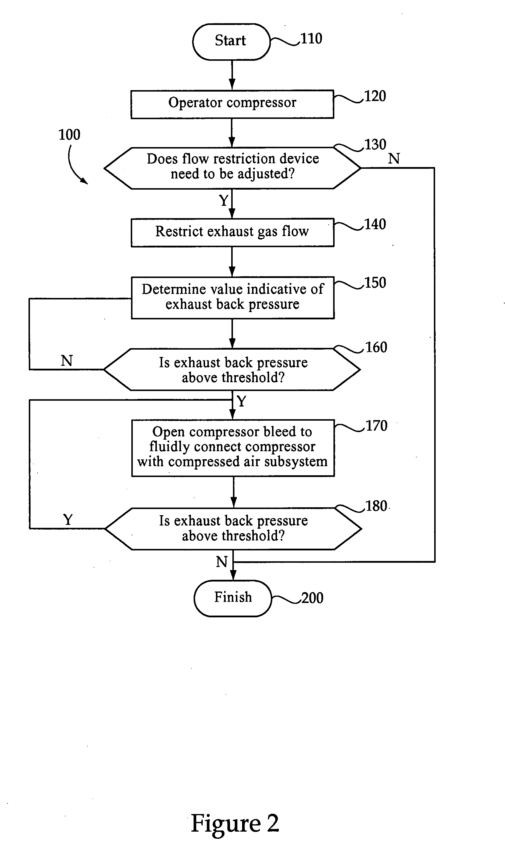
[0008]In still another aspect, the present disclosure provides a method of operating an engine system that includes the steps of compressing intake air for the engine system via a compressor, and restricting exhaust flow from the engine system at least in part via a variable flow restriction device. The method still further includes a step of, during restricting exhaust flow, supplying compressor air to a compressed air subsystem of the engine system at least in part by selectively actuating a pressure control device to fluidly connect an inlet of the compressed air subsystem with the compressor.

Problems solved by technology

Under certain operating conditions it may be difficult for a standard turbocharger to accommodate the demand for compressed air in the King et al. approach due to the design of the system.

Method used


Image

  • Machine, engine system and operating method
  • Machine, engine system and operating method
  • Machine, engine system and operating method

Examples


Embodiment Construction

[0011]Referring to FIG. 1, there is shown a machine 10 according to one embodiment of the present disclosure. Machine 10 may include a frame 12 having ground engaging elements 13, at least one of which is a drive element, and an implement system 14 mounted thereon. In the illustrated embodiment, machine 10 includes an implement system of the type commonly used with machines known in the art as telehandlers. It should be appreciated, however, that machine 10 might have a wide variety of designs. For instance, off-highway machines such as tractors, loaders, etc., as well as on-highway trucks and the like may be constructed and operated according to the teachings set forth herein. In still other embodiments, machine 10 might comprise a stationary machine such as a genset. Machine 10 may include an engine system 16, such as a compression ignition diesel engine system, having an engine housing 18 with a plurality of cylinders 46 therein. An intake air pathway 32 is provided for supplying...


PUM


Abstract

A method of operating an engine system includes compressing intake air, restricting exhaust flow from the engine via a flow restriction device, and supplying compressor air to a compressed air subsystem of the engine during restricting exhaust flow. Supplying of compressor air may occur by selectively actuating a pressure control device to fluidly connect an inlet of a compressed air subsystem with the compressor. An associated machine and engine system include a compressor, a flow restriction device, a compressed air subsystem and a pressure control device to selectively fluidly connect the compressed air subsystem with the compressor when the flow restriction device is in a relatively more closed configuration.

Description

TECHNICAL FIELD [0001]The present disclosure relates generally to machines and machine subsystems using compressed air, and relates more particularly to selectively providing compressed air to a machine subsystem during controllably restricting exhaust gas flow from an internal combustion engine.BACKGROUND [0002]A wide variety of machines, notably heavy-duty mobile machines such as construction, agricultural and transport machines utilize on-board compressed air for various purposes. Compressed air may be used for brake or implement system actuation, to power certain tools, for debris cleaning, and myriad other uses. Relatively recently, compressed air has begun to be used in conjunction with exhaust aftertreatment elements, in particular for compression ignition diesel engines.[0003]One example of an exhaust aftertreatment element utilizing compressed air is known in the art as a urea injection module. Urea acts as a reducing agent for NOx in engine exhaust. It is typically necessa...

Claims


Application Information

Patent Timeline
Patent Type & Authority Applications(United States)
IPC IPC(8): F01N3/04
CPCF01N9/00F01N9/002F01N2260/04F01N2260/06F01N2260/08Y02T10/47F01N2570/14F01N2610/02F02B37/24Y02T10/144F01N2260/14F01N2610/08F01N2610/14F01N2610/1453F02D9/04Y02T10/12Y02T10/40
Inventor CROSBY, DANIEL W.RAINA, ANIL
Owner CATERPILLAR INC
Learn More