Upper body structure for fuel cell vehicle for reinforcing floor kick-up portion

a fuel cell vehicle and upper body technology, applied in vehicle arrangements, roofs, transportation and packaging, etc., can solve the problems of monocoque body becoming weak for enduring an external force, heavy weight of humidifier and fuel cell stack in fuel cell vehicles, and now confronted by a tremendous chang

Active Publication Date: 2009-03-05
HYUNDAI MOTOR CO LTD
View PDF8 Cites 37 Cited by
  • Summary
  • Abstract
  • Description
  • Claims
  • Application Information

AI Technical Summary

Benefits of technology

[0035]The present invention has been made in an effort to solve the aforementioned problems associated with prior arts and one object of the present invention is to provide an upper body structure for a fuel cell vehicle in which the concentrated load transferred from the floor kick-up portion of the upper body through the body mounting portion of the chassis frame and the side crash load caused by the side crash are efficiently dispersed.
[0036]Another object of the present invention is to provide an upper body structure for a fuel cell vehicle in which the floor kick-up portion of the upper body is reinforced, so that vibration and transformation of vehicle body are minimized, the ride comport is improved, and the protection effect of the passenger and the hydrogen tank is maximized.

Problems solved by technology

Vehicle industry has rapidly grown centering on gasoline and diesel internal combustion engines for more than one hundred years, but it is now confronted by a tremendous change due to problems such as environmental regulations, threat to energy security and exhaustion of fossil fuel.
The humidifier and the fuel cell stack mounted in a fuel cell vehicle are very heavy in weight.
If these heavy parts are mounted in the engine room of the monocoque body, a monocoque body configured by combining very thin panels which are mold-manufactured may not endure the strength and, so the monocoque body may become very weak in durability for enduring an external force.
That is, providing the monocoque body with sufficient strength requires its structure to be more complicated.
Since hydrogen is stored in a gas state, the size of each hydrogen tank is increased, which interferes with setting a ground clearance and securing a passenger room.
In case of the fuel cell vehicle having hydrogen tank, however, it is expected that the side crash badly affects the fuel cell system due to a layout of the fuel system and the size of the hydrogen tank.

Method used


Image

  • Upper body structure for fuel cell vehicle for reinforcing floor kick-up portion
  • Upper body structure for fuel cell vehicle for reinforcing floor kick-up portion
  • Upper body structure for fuel cell vehicle for reinforcing floor kick-up portion

Examples


Embodiment Construction

[0048]Reference will now be made in detail to the embodiments of the present invention, examples of which are illustrated in the accompanying drawings, wherein like reference numerals refer to the like elements throughout. The embodiments are described below in order to explain the present invention by referring to the figures.

[0049]The present invention relates to improvement of a member structure which constitutes the lower vehicle body of the upper body to reinforce the floor kick-up portion of the upper body in a vehicle body of a fuel cell vehicle.

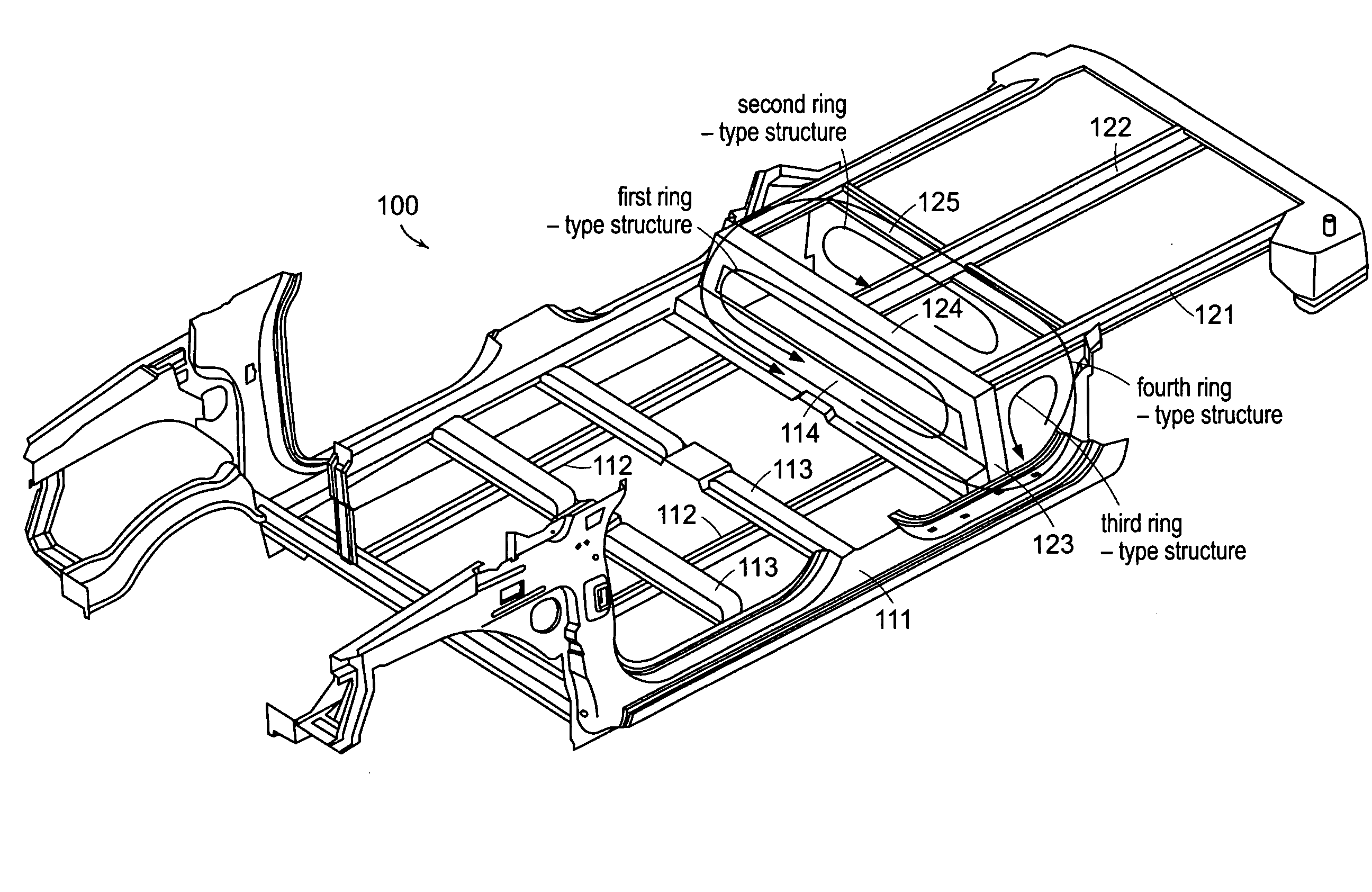
[0050]FIG. 3 is a perspective view illustrating a vehicle body structure of a fuel cell vehicle according to an exemplary embodiment of the present invention. Particularly, FIG. 3 shows the lower vehicle structure of the upper body.

[0051]As shown in FIG. 3, a lower portion of the upper body 100 comprises a plurality of members which are horizontally (transversely) or longitudinally arranged to be combined with each other.

[0052]Side si...


PUM


Abstract

An upper body structure for a fuel cell vehicle for reinforcing a floor kick-up portion is disclosed. The upper body structure for the fuel cell vehicle includes: a center floor rear cross member (114) horizontally arranged in a lower portion of the floor kick-up portion and connecting side sills (111) arranged on both sides of the upper body; two rear floor front side members (123) arranged in an up-down direction on both sides of the upper body and having lower ends connected to both ends of the center floor rear cross member (114); and a rear floor front cross member (124) horizontally arranged in an upper portion of the floor kick-up portion and connecting upper ends of the two rear floor front side members (123), wherein the center floor rear cross member (114), the two rear floor front side members (123) and the rear floor front side member (124) form a first ring-type structure.

Description

CROSS-REFERENCE TO RELATED APPLICATION[0001]This application claims the benefit under 35 U.S.C. §119(a) on Korean Patent Application No. 10-2007-88769, filed on Sep. 3, 2007, the entire contents of which are incorporated herein by reference.BACKGROUND[0002]1. Technical Field[0003]The present invention relates to a vehicle body structure for a fuel cell vehicle, and more particularly, to a vehicle body of a fuel cell vehicle including a lower vehicle body structure of an upper body for reinforcing a floor kick-up portion.[0004]2. Background Art[0005]Vehicle industry has rapidly grown centering on gasoline and diesel internal combustion engines for more than one hundred years, but it is now confronted by a tremendous change due to problems such as environmental regulations, threat to energy security and exhaustion of fossil fuel.[0006]Many developed countries have entered into competition of developing future vehicles with environment-friendly, high efficient and high-tech features, a...

Claims


Application Information

Patent Timeline
Patent Type & Authority Applications(United States)
IPC IPC(8): B62D25/20B62D21/00
CPCB62D25/20B62D21/00B62D21/02
Inventor PARK, TAE WAN
Owner HYUNDAI MOTOR CO LTD
Why Eureka
Try Eureka