Foam seat element, mold for the production thereof and method to manufacture the mold

a seat element and foam technology, applied in the field of foam seat elements, can solve the problems of increasing the production time and cost of the final seat product, difficulty in providing balance support, and high cost of dual density or dual firmness seat elements, and achieve the effect of increasing density

Inactive Publication Date: 2009-03-05
PROPRIETECT LP
View PDF11 Cites 11 Cited by
  • Summary
  • Abstract
  • Description
  • Claims
  • Application Information

AI Technical Summary

Benefits of technology

[0024]In a further preferred embodiment, the present seat element comprises a molded foam seat element, more preferably a molded foam element comprising a unitary foam portion. An advantage of using such a molded foam element in the present seat element is the presence of a skin on the surface of the seating surface element. The presence of the skin is characterized by the foam having a greater density at the surface (e.g., 1 mm depth) as compared to the central or core region. Density can be determined using ASTM D-3574. While not wishing to be bound by any particular theory or mode of action, it is believed that the presence of such a skin (e.g., as distinct from the case where the peaks are simply glued to and / or the valleys are simply cut out of the seating surface element) confers a desirable combination of support and comfort to an occupant of the seat element.

Problems solved by technology

However, there is an ongoing challenge to balance support provided by the seat with comfort of the occupant.
Dual density or dual firmness seat elements are expensive to produce and, in many cases, alter the feel of the supporting surface of the seat only in areas where it is perceived to be important to have different firmness properties.
Further, dual (or multi) density or dual (or multi) firmness seats typically require the use of two or more types of foam (e.g., molded, free rise, bead and the like) which are typically produced separately and secured together increasing the production time and costs of the final seat product.

Method used


Image

  • Foam seat element, mold for the production thereof and method to manufacture the mold
  • Foam seat element, mold for the production thereof and method to manufacture the mold
  • Foam seat element, mold for the production thereof and method to manufacture the mold

Examples


Embodiment Construction

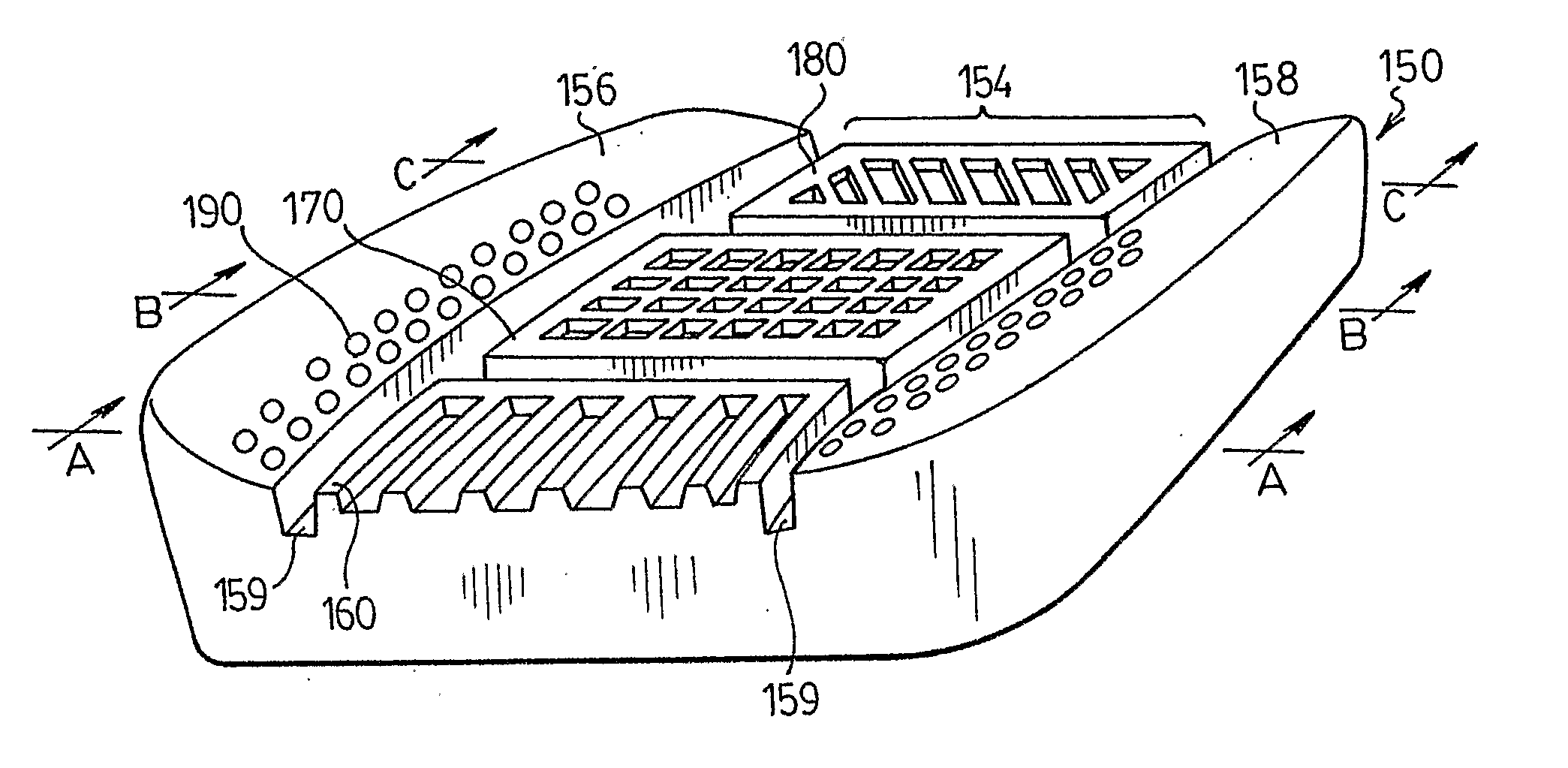
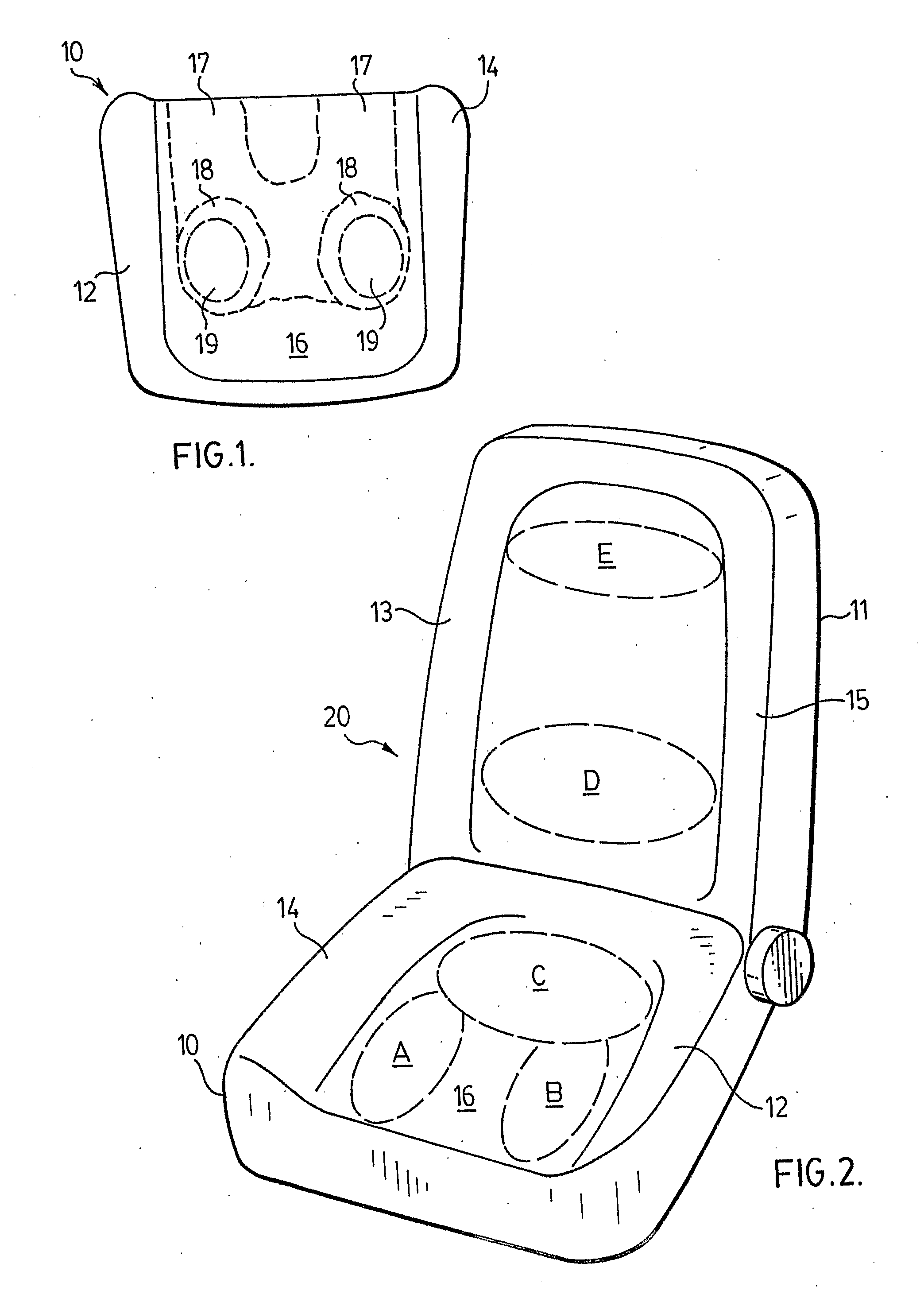
[0054]Accordingly, an aspect of the present invention relates to a seat element. Preferably, a seat element is comprised in a vehicular or passenger seat. As used throughout this specification, the term “seat” is intended to have its conventional meaning and includes one or both of a bottom or cushion (i.e., the portion of the seat on which the occupant sits) and a back or backrest (i.e., the portion of the seat which supports the back of the occupant). As is known in the automotive, airline and related industries, a “seat” includes both a cushion (or bottom) and a back (or backrest). Thus, the term “seat” includes a seat element such as a cushion (or bottom), a back (or backrest) or a unit construction comprising a cushion (or bottom) and a back (or backrest). It should also be mentioned that a seat element may be considered to be a cushion (or bottom), a back (or backrest), a headrest and / or an armrest.

[0055]While highly preferred embodiments of the present invention will be illus...


PUM

PropertyMeasurementUnit
shapeaaaaaaaaaa
densityaaaaaaaaaa
speedaaaaaaaaaa

Abstract

There is disclosed an improved seat element having a seating surface element that incorporates a plurality of peak portions and a plurality of valley portions. Preferably, the plurality of peak portions and the plurality of valley portions is incorporated in an outermost surface of the seating surface element. The term “outermost surface” is intended to include an area of the seating surface element for contact by and/or support of an occupant of the seat element and does not include, for example, grooves or trenches in which there is disposed a component for attachment of a trim cover. A process and a mold for production of such a seat element are also described.

Description

FIELD OF THE INVENTION[0001]In one of its aspects, the present invention relates to a foam seat element, preferably a foam vehicular seat element. In another of its aspects, the present invention relates to a process for producing a foam seat element, preferably a vehicular seat element. In yet another of its aspects, the present invention relates to a mold for producing a molded element, preferably a molded foam seat element, more preferably a molded foam vehicular seat element. In yet another of its aspects, the present invention relates to a method for producing a mold.DESCRIPTION OF THE PRIOR ART[0002]Passenger seats in vehicles, such as automobiles, are typically fabricated from a foam (usually a polyurethane foam) material which is molded into the desired shape and covered with an appropriate trim cover. The foamed material is selected to provide passenger comfort by providing a resilient seat and the trim cover is selected to provide the desired aesthetic properties.[0003]In ...

Claims


Application Information

Patent Timeline
Patent Type & Authority Applications(United States)
IPC IPC(8): A47C7/18B29D99/00B60N2/90
CPCA47C7/18B29C33/424B60N2/70A47C27/146B60N2/7017B29C33/42B29C33/38B29D99/00
Inventor SAN MIGUEL, EDGARDO A.MAGEE, ROBERT B.CLARCK, LESLIE E.MILLER, DAVID J. L.GENYN, LARRY A.
Owner PROPRIETECT LP
Why Eureka
Try Eureka