Hybrid vehicle and method of controlling the same

a hybrid vehicle and control method technology, applied in the direction of electric energy management, driver input parameters, gas pressure propulsion mounting, etc., can solve the problem of finding abnormalities in the second motive power source, and achieve the effect of reducing the size of the vehicle, improving fuel efficiency, and good condition

Active Publication Date: 2009-03-05
TOYOTA JIDOSHA KK
View PDF8 Cites 42 Cited by
  • Summary
  • Abstract
  • Description
  • Claims
  • Application Information

AI Technical Summary

Benefits of technology

[0010]The present invention is therefore made to solve such problems, and an object of the present invention is to provide a hybrid vehicle capable of forcedly operating a motive power source with reduced operation frequency.

Problems solved by technology

In addition, an abnormality in the second motive power source can be discovered at an early stage, if it occurs.

Method used


Image

  • Hybrid vehicle and method of controlling the same
  • Hybrid vehicle and method of controlling the same
  • Hybrid vehicle and method of controlling the same

Examples


first embodiment

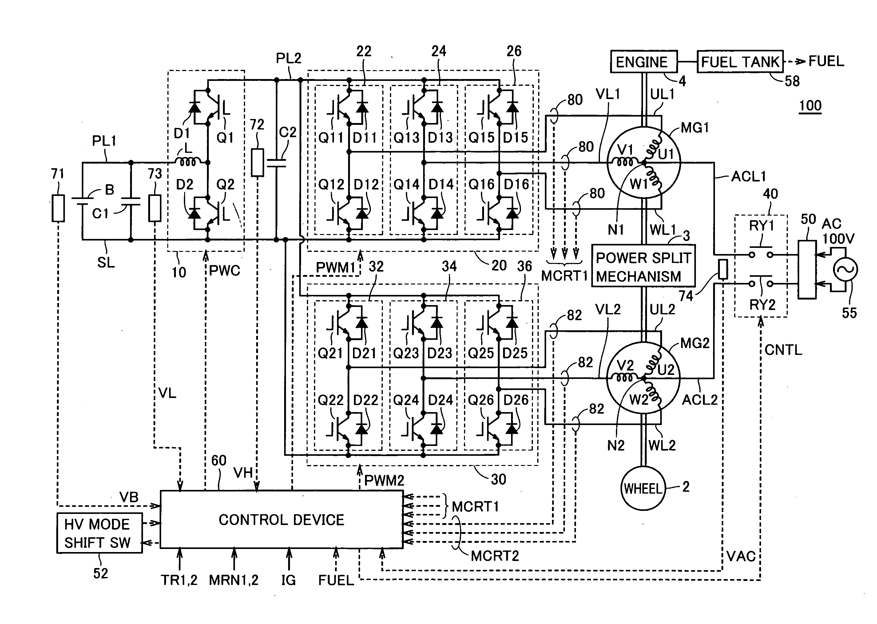
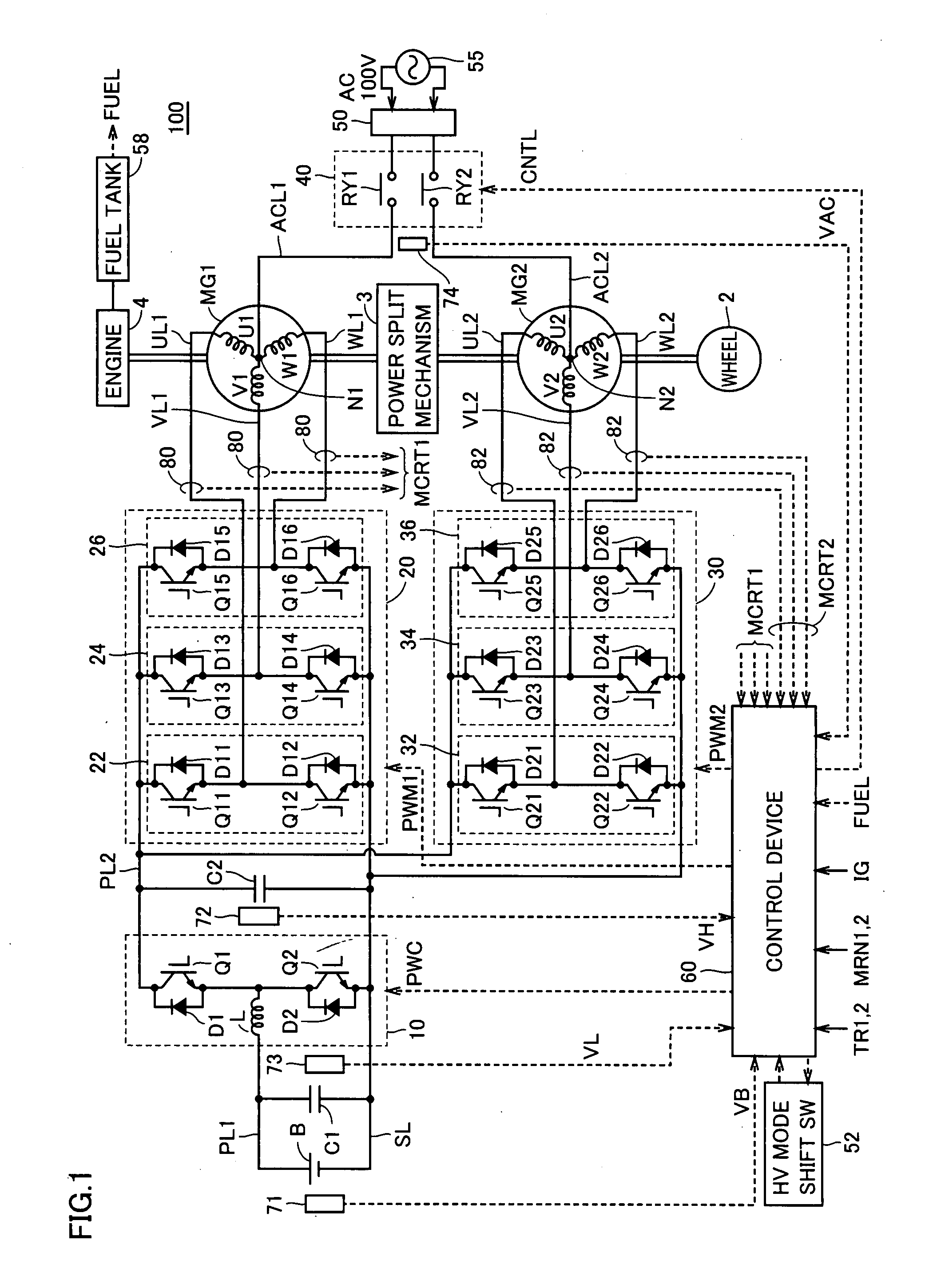
[0046]FIG. 1 is an entire block diagram of a hybrid vehicle in accordance with a first embodiment of the present invention. Referring to FIG. 1, a hybrid vehicle 100 includes an electricity storage device B, a boost converter 10, inverters 20, 30, power supply lines PL1, PL2, a ground line SL, U-phase lines UL1, UL2, V-phase lines VL1, VL2, W-phase lines WL1, WL2, motor generators MG1, MG2, an engine 4, a fuel tank 58, a power split mechanism 3, and a wheel 2.

[0047]Engine 4 receives supply of fuel from fuel tank 58 to generate motive power. Fuel tank 58 supplies fuel to engine 4. Fuel tank 58 also detects the remaining amount of fuel and outputs a signal FUEL indicating the remaining amount of fuel to a control device 60 as described later.

[0048]Power split mechanism 3 is a mechanism that is linked to engine 4 and motor generators MG1, MG2 to split power therebetween. For example, as power split mechanism 3, a planetary gear train having three rotational axes of a sun gear, a planet...

second embodiment

[0147]FIG. 14 is a schematic block diagram of a hybrid vehicle in accordance with a second embodiment of this invention. Referring to FIG. 14, a hybrid vehicle 100A includes electricity storage device B, boost converter 10, a fuel cell 90, a hydrogen tank 92, inverter 30, motor generator MG2, wheel 2, HV mode shift switch 52, a control device 60A, and capacitors C1, C2.

[0148]Fuel cell 90 is a direct-current power generation battery to obtain electric energy from chemical reaction energy produced by a chemical reaction of hydrogen supplied from hydrogen tank 92 with oxidant. Fuel cell 90 is connected to power supply line PL2 and ground line SL to supply the generated direct-current power to power supply line PL2.

[0149]In other words, this hybrid vehicle 100A has an electric power source having a hybrid structure of electricity storage device B and fuel cell 90. Hybrid vehicle 100A in accordance with this second embodiment can be regarded as having a motive power source comprised of f...


PUM

PropertyMeasurementUnit
charging voltageaaaaaaaaaa
electric poweraaaaaaaaaa

Abstract

A hybrid automobile, wherein a second power source operated with less frequency can be forcibly operated. The hybrid automobile comprises a storage battery as a first power source. The hybrid automobile further comprises an engine and a motor generator or a fuel cell as the second power source. When the hybrid automobile is run by the first power source, a driver can change over an operation mode to a running by the second power source by operating an input device. The hybrid automobile further comprises a notification means for prompting the driver to operate the input device when the non-operating time of the second power source exceeds a predetermined time or longer. Furthermore, the hybrid automobile comprise a control means which, when the remaining amount of energy of the second power source is less than a predetermined amount, stops the changeover of the operation mode from a running by the first power source to the running by the second power source.

Description

TECHNICAL FIELD[0001]The present invention relates to a hybrid vehicle, and more particularly to a hybrid vehicle capable of traveling while switching between a hybrid mode of traveling by driving a plurality of motive power sources and an electric vehicle mode of traveling only using electric power from an electricity storage device.BACKGROUND ART[0002]Recently, hybrid vehicles have received great attention against the background of environmental issues. A hybrid vehicle is a vehicle on which a plurality of motive power sources are mounted, and a hybrid vehicle using an electricity storage device (battery, capacitor or the like) and a motor, in addition to a conventional engine, as motive power sources has already been put into practice.[0003]Furthermore, a fuel cell vehicle on which a fuel cell is mounted as a motive power source also receives attention. A vehicle equipped with an electricity storage device such as a battery or a capacitor, in addition to a fuel cell, as an electr...

Claims


Application Information

Patent Timeline
Patent Type & Authority Applications(United States)
IPC IPC(8): H02P5/74H02P27/06B60K6/26B60K6/28B60K6/445B60K8/00B60L50/11B60L50/15B60L50/16B60W10/06B60W10/08B60W10/26B60W10/28B60W20/00F02D29/06H01M8/00
CPCB60K1/02B60Y2300/476B60K6/445B60L11/123B60L11/14B60L11/1887B60L2210/20B60L2240/80B60L2260/26B60W10/06B60W10/08B60W10/26B60W10/28B60W20/00B60W2510/244B60W2540/04H01M16/006H02P2201/09Y02T10/54Y02T10/56Y02T10/6217Y02T10/6269Y02T10/6286Y02T10/642Y02T10/7005Y02T10/7077Y02T10/725Y02T90/34Y02T10/6239B60K6/32B60L50/61B60L50/16B60L58/40B60W2540/215Y02T10/40Y02T10/62Y02T10/64Y02T10/70Y02T10/72Y02T10/7072Y02T90/40Y02E60/50Y02E60/10B60W50/082B60W50/085Y02T10/84B60W20/10
Inventor OYOBE, HICHIROSAINAKAMURA, MAKOTO
Owner TOYOTA JIDOSHA KK
Why Eureka
Try Eureka