High-frequency module, and mobile telephone and electronic device provided therewith
a high-frequency module and mobile telephone technology, applied in the field of high-frequency modules, can solve the problems of reducing the battery reducing the service life of an appliance, and deteriorating distortion performance of the amplifier circuit, so as to improve the reception sensitivity and increase the consumption current and cost
- Summary
- Abstract
- Description
- Claims
- Application Information
AI Technical Summary
Benefits of technology
Problems solved by technology
Method used
Image
Examples
first embodiment
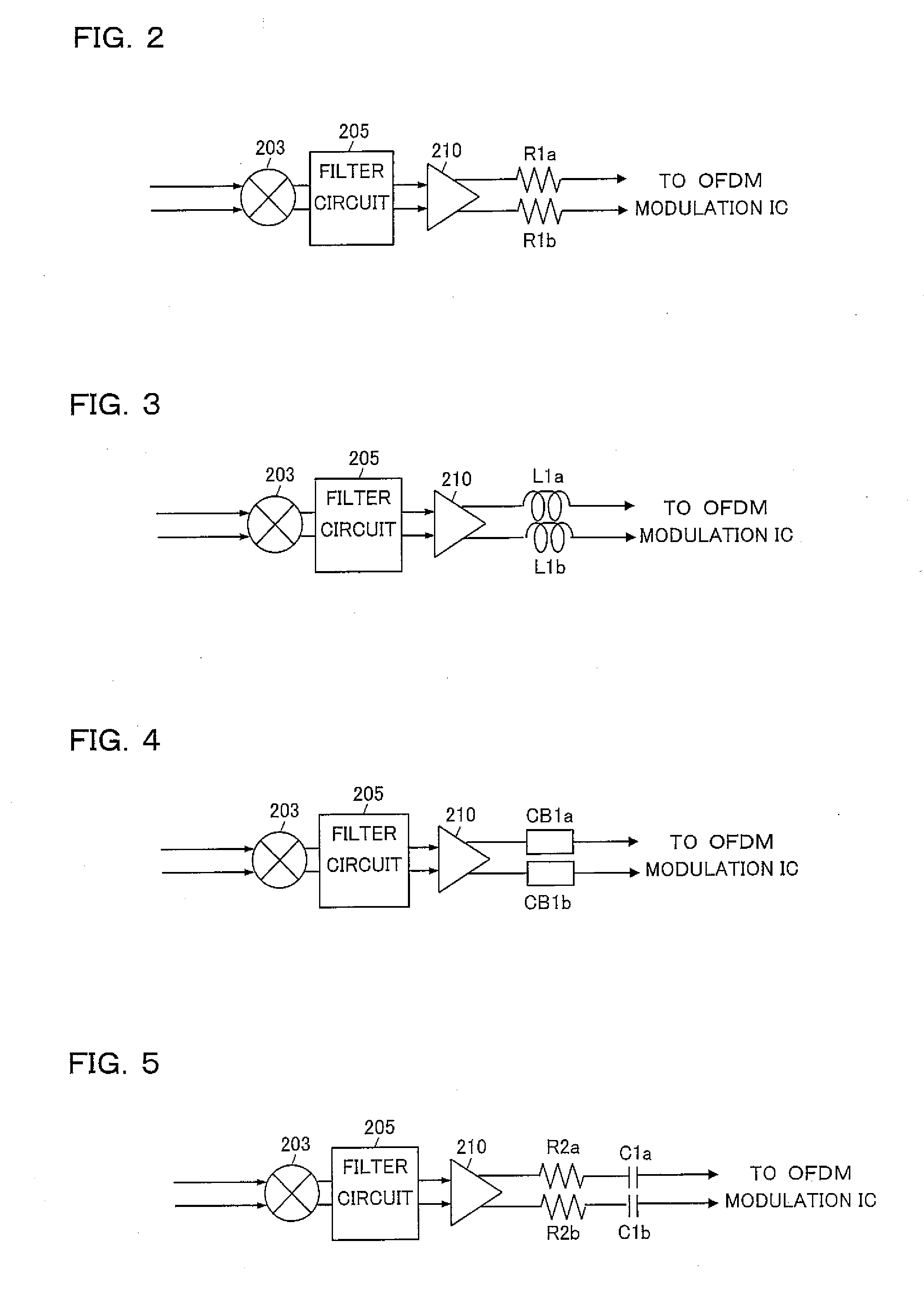
[0047]FIG. 2 is a circuit diagram showing the one-segment tuner module 1 of a
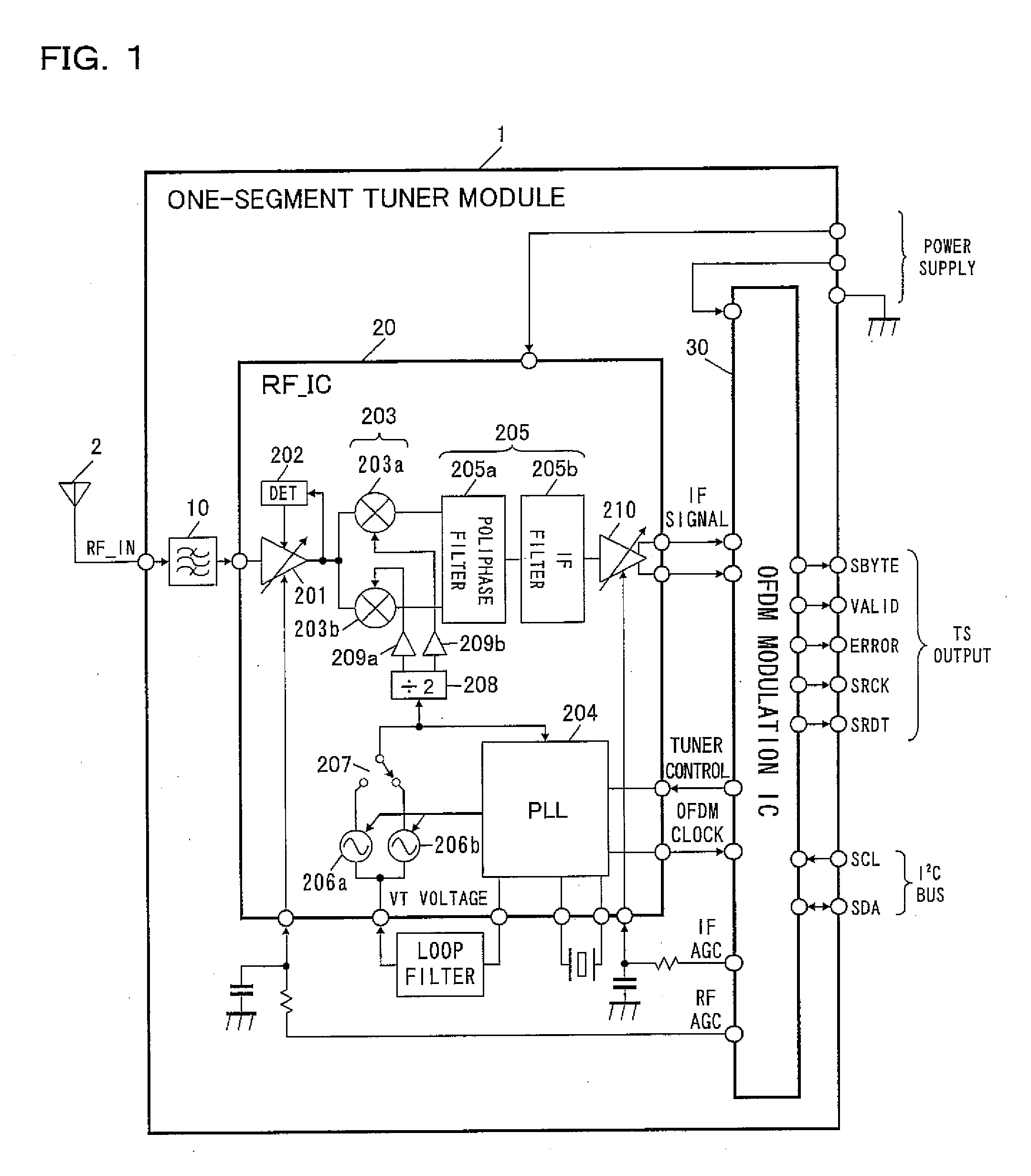
[0048]As shown in FIG. 2, in the one-segment tuner module 1 of the first embodiment, one or more resistive elements (resistors R1a and R1b in FIG. 2) are interposed in series between the output terminals of the IF_VGA circuit 210 and the input terminals of the OFDM modulation IC 30 in the stage succeeding the IF_VGA circuit 210.
[0049]By interposing the resistors R1a and R1b in this way, it is possible to apparently increase the input impedance of the OFDM modulation IC 30 as seen from the IF_VGA circuit 210.
[0050]The resistance of the resistors R1a and R1b is preferably about 100Ω, as experimentally found; even when the input impedance of the OFDM modulation IC 30 is as low as about 100Ω, the apparent input impedance of the OFDM modulation IC 30 is increased to about 300Ω by interposing the resistors R1a and R1b.
[0051]Hence, without increased consumption current and cost, the influence from the succeeding ...
second embodiment
[0054]FIG. 3 is a circuit diagram showing the one-segment tuner module 1 of a
[0055]As shown in FIG. 3, in the one-segment tuner module 1 of the second embodiment, one or more inductance elements (coils L1a and L1b in FIG. 3) are interposed in series between the output terminals of the IF_VGA circuit 210 and the input terminals of the OFDM modulation IC 30 in the stage succeeding the IF_VGA circuit 210.
[0056]By interposing the coils L1a and L1b in this way, it is possible to apparently increase the input impedance of the OFDM modulation IC 30 as seen from the IF_VGA circuit 210.
[0057]The second embodiment where the inductance elements are interposed differs from the first embodiment where the resistive elements are interposed in that a LPF (low pass filter) is formed by input capacitance (unillustrated) of the OFDM modulation IC 30 and the interposed inductance elements. Thus, it is possible to reduce the distortion, and the harmonic components in it in particular, occurring in the I...
third embodiment
[0058]FIG. 4 is a circuit diagram showing the one-segment tuner module 1 of a
[0059]As shown in FIG. 4, in the one-segment tuner module 1 of the third embodiment, one or more chip beads (chip beads CB1a and CB1b in FIG. 4) are interposed in series between the output terminals of the IF_VGA circuit 210 and the input terminals of the OFDM modulation IC 30 in the stage succeeding the IF_VGA circuit 210.
[0060]By interposing the chip beads CB1a and CB1b in this way, as in the first and second embodiments, it is possible to apparently increase the input impedance of the OFDM modulation IC 30 as seen from the IF_VGA circuit 210.
[0061]The third embodiment where the chip beads are interposed differs from the second embodiment where the inductance elements are interposed in that a LPF is formed by chip beads alone irrespective of the input capacitance of the OFDM modulation IC 30. Thus, it is possible to stably obtain the benefits of the present invention with little variation in results.
PUM
 Abstract
Description
Claims
Application Information
 - R&D
- Intellectual Property
- Life Sciences
- Materials
- Tech Scout
- Unparalleled Data Quality
- Higher Quality Content
- 60% Fewer Hallucinations
Browse by: Latest US Patents, China's latest patents, Technical Efficacy Thesaurus, Application Domain, Technology Topic, Popular Technical Reports.
© 2025 PatSnap. All rights reserved.Legal|Privacy policy|Modern Slavery Act Transparency Statement|Sitemap|About US| Contact US: help@patsnap.com


