Primary radiator for parabolic antenna, low noise block down-converter, and parabolic antenna apparatus

a technology of parabolic antenna and radiator, which is applied in the direction of antennas, waveguide horns, radiating element housings, etc., can solve the problems of difficult to achieve cross polarization characteristics not less than 23 db for the overall antenna, and hardly suppress the vswr, so as to achieve good cross polarization characteristics , the radiation angle at the primary radiator can be made larger , the effect of good cross polarization characteristics

Inactive Publication Date: 2009-03-05
SHARP KK
View PDF6 Cites 8 Cited by
  • Summary
  • Abstract
  • Description
  • Claims
  • Application Information

AI Technical Summary

Benefits of technology

[0020]According to the primary radiator for a parabolic antenna of the present invention, by forming the height of the inner cylindrical portion higher than the height of the outer cylindrical portion, the inner and higher cylindrical portion can suppress the VSWR at a low frequency and the outer and lower cylindrical portion can suppress the VSWR at a high frequency, such that the input VSWR is effectively suppressed over a wide range of bandwidths of 300 MHz-1050 MHz. Moreover, the cross polarization characteristics of a subsequent block connected to the primary radiator is not deteriorated such that the good cross polarization characteristics of not less than 23 dB can be implemented.
[0021]Moreover, by circumferentially forming the annular step portion which is low...

Problems solved by technology

However, above-described conventional primary radiator 110 for a parabolic antenna has a problem that it can hardly suppress the VSWR at the frequency with a bandwidth of up to 1050 MHz though it can suppress the VSWR at the frequency with a bandwi...

Method used


Image

  • Primary radiator for parabolic antenna, low noise block down-converter, and parabolic antenna apparatus
  • Primary radiator for parabolic antenna, low noise block down-converter, and parabolic antenna apparatus
  • Primary radiator for parabolic antenna, low noise block down-converter, and parabolic antenna apparatus

Examples


first embodiment

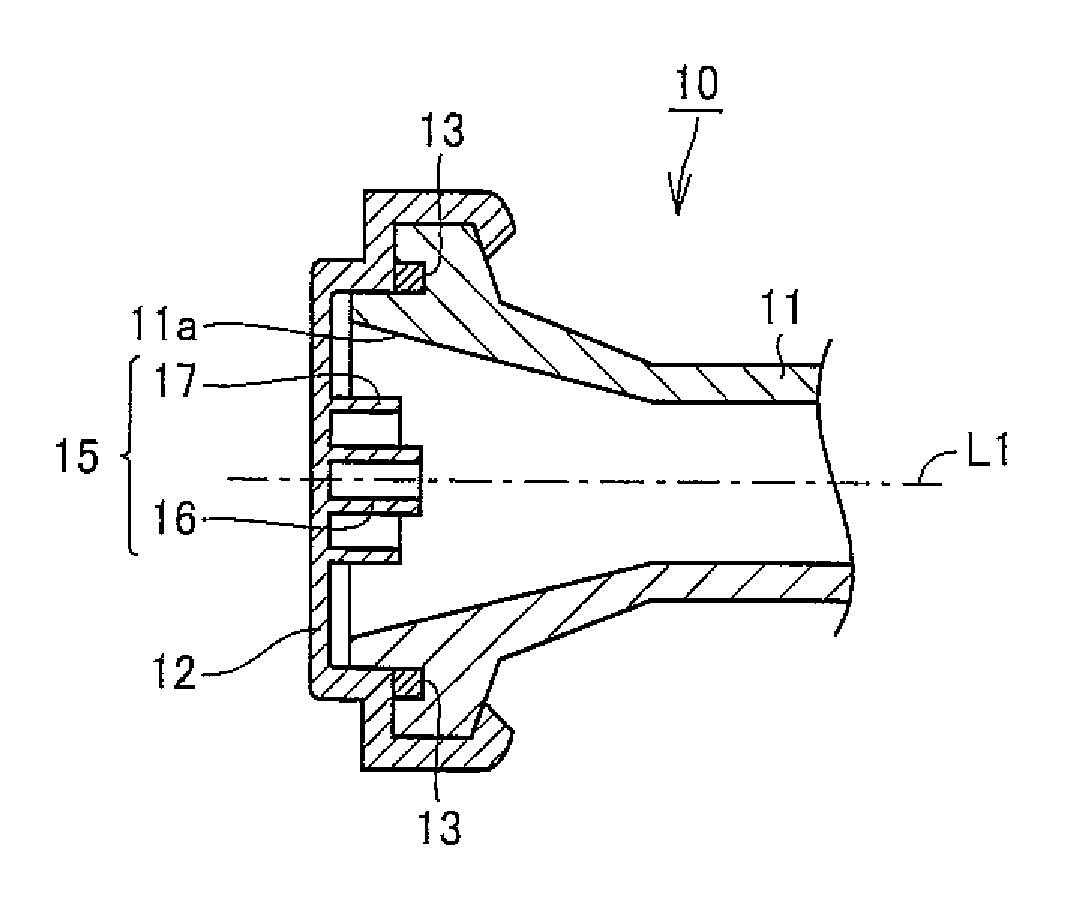
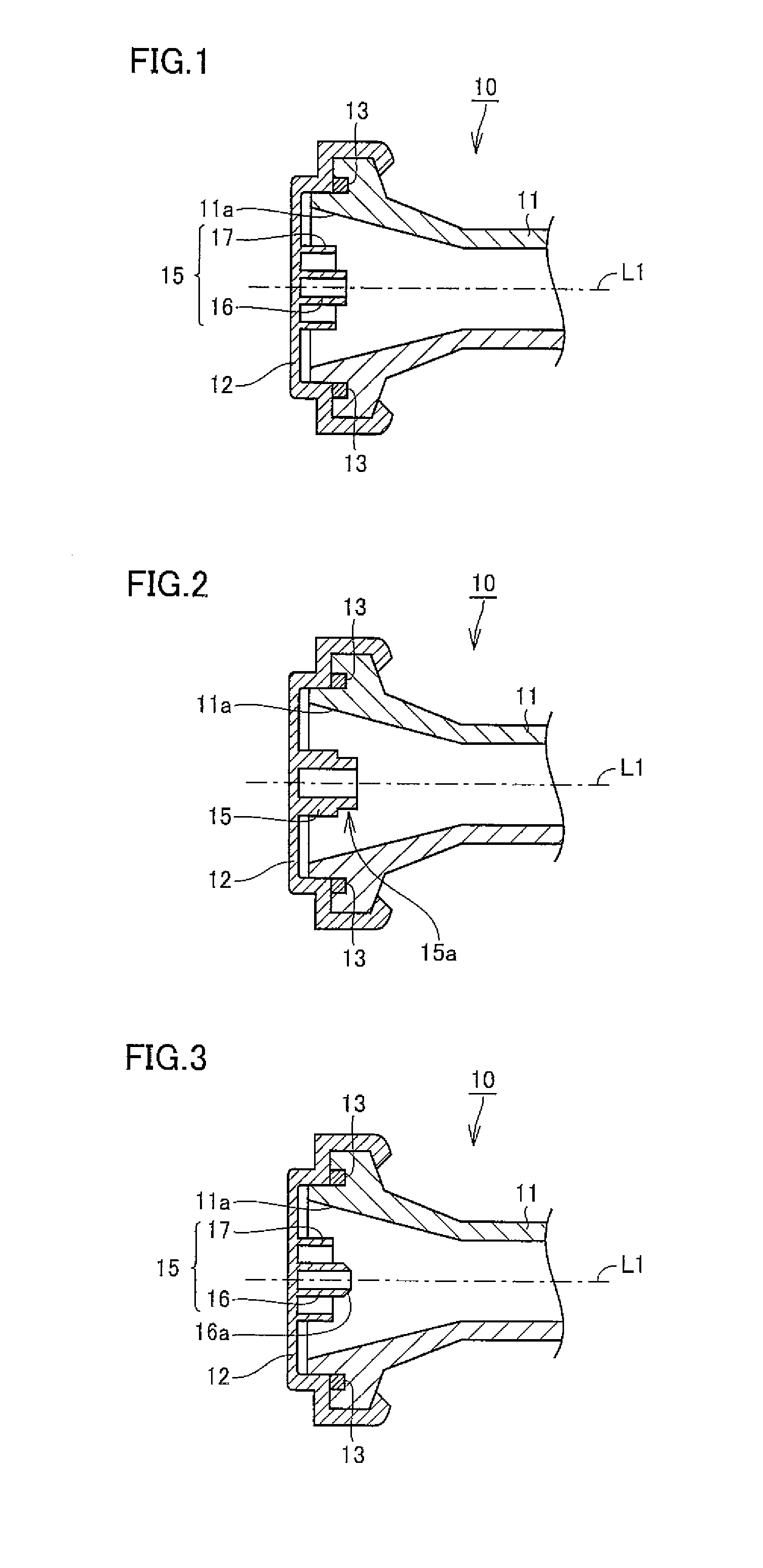
[0033]Although a case where two cylindrical portions are concentrically provided as one protruding portion is shown in the above first embodiment, the same effect can be achieved by concentrically providing three or more cylindrical portions and setting the height of an inner cylindrical portion higher than the height of an outer cylindrical portion.

[0034]A second embodiment of the present invention will now be described based on FIG. 2. Cylindrical protruding portion 15 formed of a dielectric is provided on the inner wall surface of horn cap 12 of the second embodiment, and arranged concentrically with the central axis of horn antenna body 11. In addition, an annular step portion 15a is circumferentially formed in the vicinity of an open end of protruding portion 15.

[0035]Owing to this step portion 15a, the VSWR at a high frequency can be suppressed such that the input VSWR is effectively suppressed over a wide range of bandwidths of 300 MHz-1050 MHz. Moreover, the cross polarizati...

third embodiment

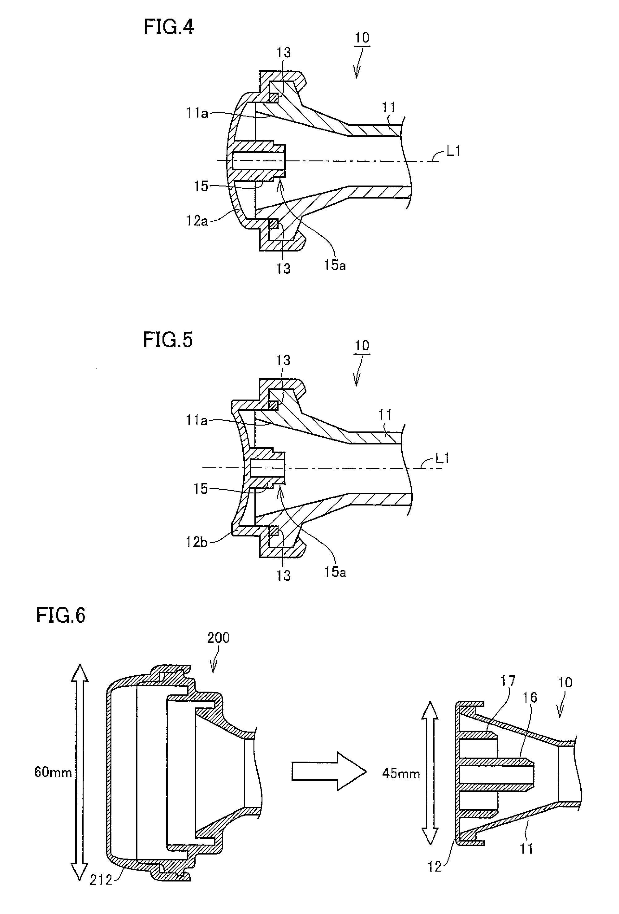
[0037]Although an example in which a tapered portion is formed at the open end of only inner cylindrical portion 16 is shown in the third embodiment, a tapered portion may be formed at open ends of both inner and outer cylindrical portions, as shown in a cross sectional view on the right-hand side of FIG. 6. According to the structure shown on the right-hand side of FIG. 6, the diameter of horn cap 12 can be as small as 45 mm, with respect to the diameter of 60 mm of a feed horn cap 212 of a conventional corrugated feed horn 200 shown on the left-hand side of the same drawing, thereby allowing downsizing of the primary radiator.

[0038]A cross sectional structure of a primary radiator according to a fourth embodiment of the present invention is shown in FIG. 4. In the fourth embodiment, an end plate 12a of horn cap 12 is of an outwardly curved convex shape, thereby suppressing the VSWR. Moreover, a cross sectional structure of a primary radiator according to a fifth embodiment of the ...

fourth embodiment

[0039]The radiation patterns for the conventional conical feed horn, shown in FIG. 10, are shown in FIGS. 7A, 7B and 7C, and the radiation patterns for the conical feed horn according to the present invention, shown in FIG. 4, are shown in FIGS. 8A, 8B and 8C, respectively. FIGS. 7A and 8A show a case where the frequency of a signal is 10.7 GHz, FIGS. 7B and 8B show a case where the frequency of the signal is 11.7 GHz, FIGS. 7C and 8C show a case where the frequency of the signal is 12.75 GHz, respectively. In these diagrams of radiation patterns, the horizontal axis expresses the radiation angle, and the vertical axis expresses the relative level (dB). Note that the pattern referred to as an “E-plane” through FIGS. 7A-8C shows a radiation pattern which is parallel to an electric field generated inside the feed horn (inside the circular waveguide), and the pattern referred to as an “H-plane” shows a radiation pattern which is vertical to the electric field.


PUM


Abstract

A primary radiator for a parabolic antenna includes a cylindrical horn antenna body widened towards an end opening in a cone shape, a horn cap provided at the end opening of the horn antenna body, and a plurality of cylindrical protruding portions formed of a dielectric. The protruding portions are provided on the inner wall surface of the horn cap, concentric with a central axis of the horn antenna body, and concentrically arranged with each other, and the height of an inner one is determined to be higher than an outer one. According to such a configuration, a primary radiator for a parabolic antenna configured to favorably suppress the VSWR up to a bandwidth of 1050 MHz can be provided.

Description

[0001]This nonprovisional application is based on Japanese Patent Application No. 2007-226204 filed on Aug. 31, 2007, with the Japan Patent Office, the entire contents of which are hereby incorporated by reference.BACKGROUND OF THE INVENTION[0002]1. Field of the Invention[0003]The present invention relates to a primary radiator for a parabolic antenna, a low noise block down-converter (hereinafter referred to as an “LNB”) and a parabolic antenna apparatus for a satellite broadcast using the radiator and the LNB, in particular to a structure of the primary radiator for improving the VSWR (voltage standing wave ratio).[0004]2. Description of the Background Art[0005]A schematic diagram of a common parabolic antenna is shown in FIG. 9, and a cross sectional view of a conventional primary radiator for a parabolic antenna is shown in FIG. 10. When a satellite broadcast is received by a parabolic antenna, signals S of about 12 GHz band reflected by an antenna unit 1 are collected at an ope...

Claims


Application Information

Patent Timeline
IPC IPC(8): H01Q13/02
CPCH01Q1/42H01Q19/132H01Q19/08H01Q13/02
Inventor SHIMOI, HIROSHIOKU, TOSHIAKI
Owner SHARP KK
Why Eureka
Try Eureka