
Optical film, manufacturing method of the same, and display device having the optical film

a manufacturing method and optical film technology, applied in the field of optical film, can solve the problems of increasing the production of pdp display devices and complicating the manufacturing process, and achieve the effect of reducing production costs and simple manufacturing methods

Inactive Publication Date: 2009-03-05
SAMSUNG ELECTRONICS CO LTD
View PDF6 Cites 6 Cited by
  • Summary
  • Abstract
  • Description
  • Claims
  • Application Information

AI Technical Summary

Benefits of technology

[0009]Accordingly, it is an aspect of the present invention to provide an optical film of which a manufacturing method is simple and a production cost is reduced.
[0010]Another aspect of the present invention is to provide a manufacturing method of an optical film whose manufacturing method is simple and production cost is reduced.

Problems solved by technology

However, those optical films are expensive, causing an increase in the production of the PDP display device as well as making the manufacturing process complicate.

Method used


Image

  • Optical film, manufacturing method of the same, and display device having the optical film
  • Optical film, manufacturing method of the same, and display device having the optical film
  • Optical film, manufacturing method of the same, and display device having the optical film

Examples


Embodiment Construction

[0037]Reference will now be made in detail to the embodiments of the present invention, examples of which are illustrated in the accompanying drawings, wherein like reference numerals refer to like elements throughout. The embodiments are described below so as to explain the present invention by referring to the figures.

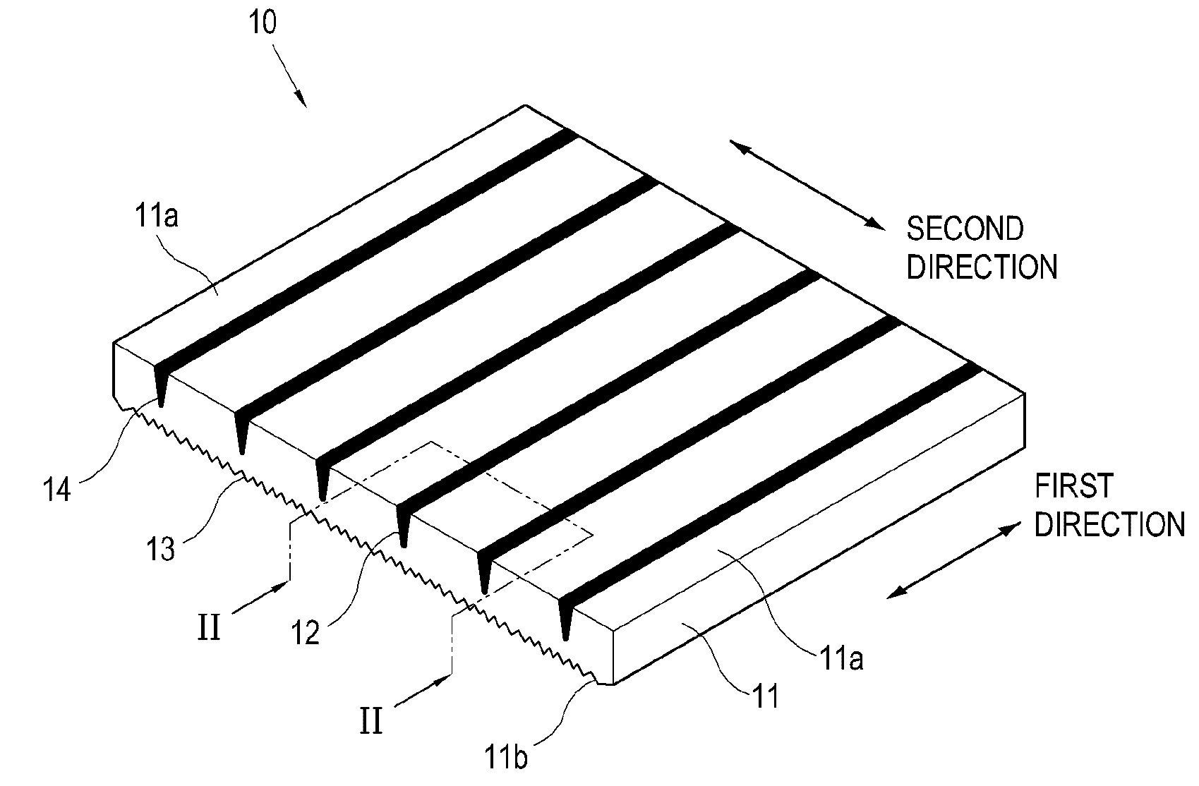
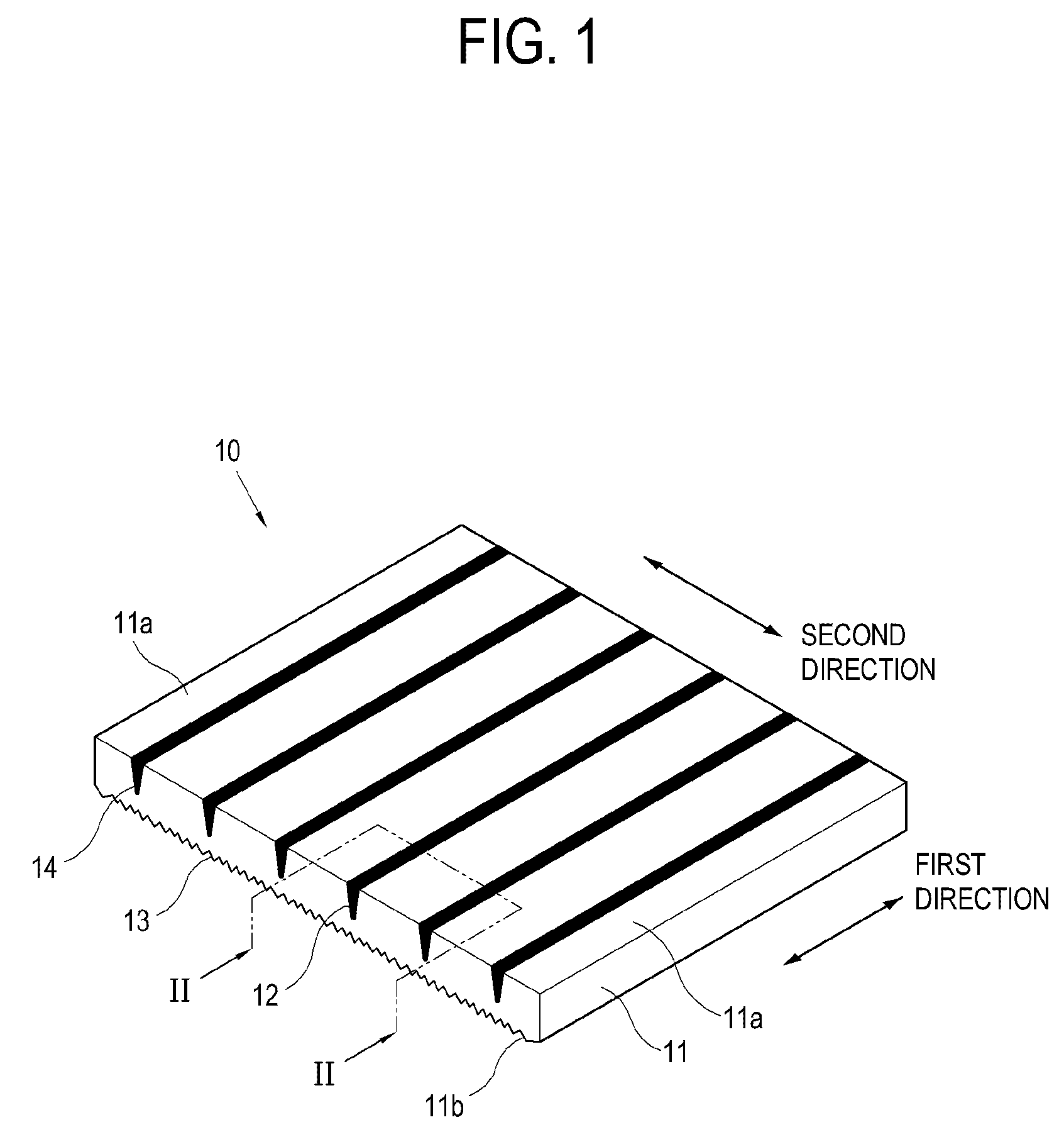
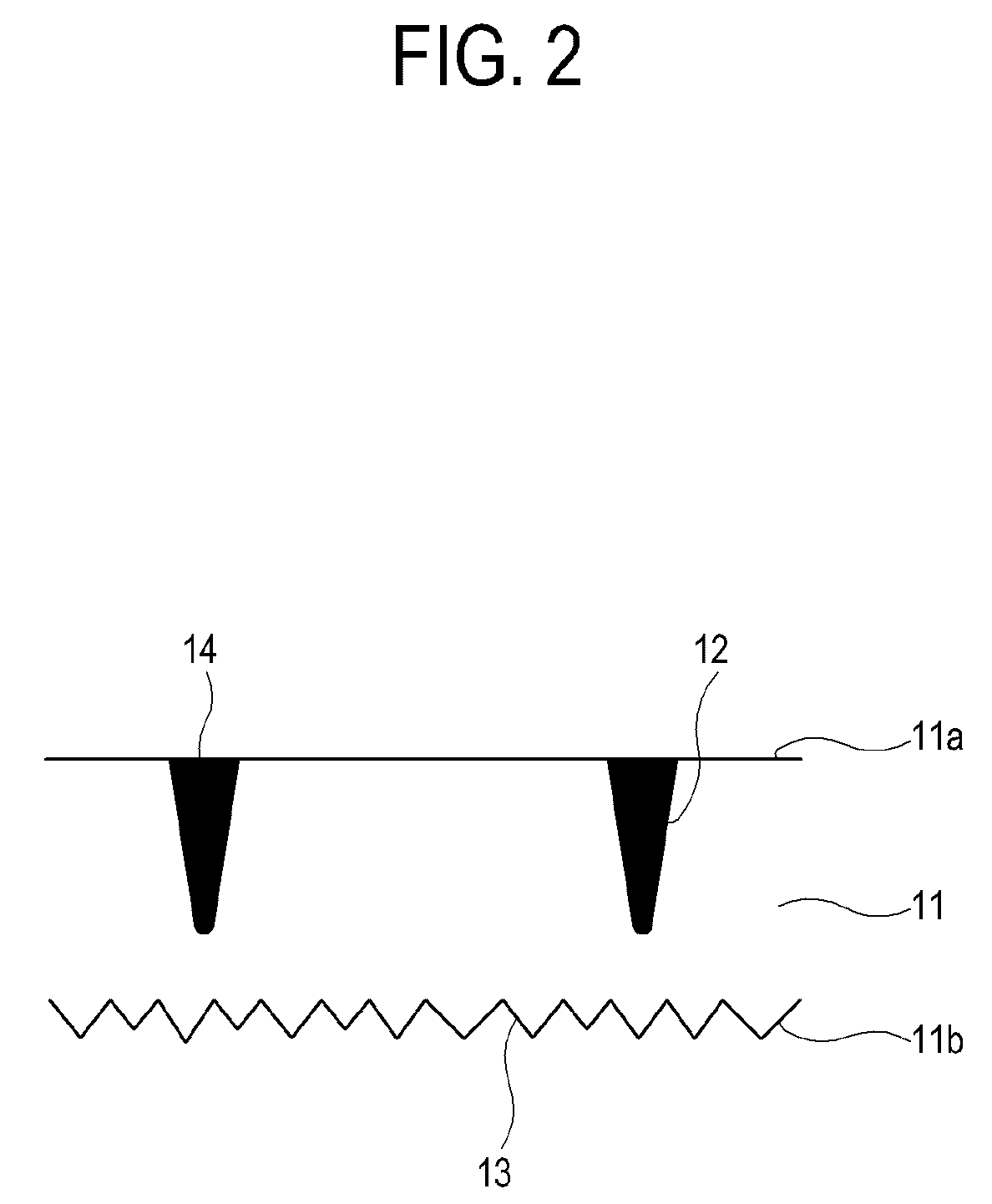
[0038]An optical film according to a first exemplary embodiment of the present invention will be described below with reference to FIGS. 1 and 2.

[0039]An optical film 10 includes a film body 11 and a light absorption member 14. The film body 11 is made of a transparent resin. The transparent resin may have a glass transition temperature of from 90 to 180° C. In an embodiment, the transparent resin has a glass transition temperature of from 120 to 180° C. The transparent resin may include, a homopolymer or copolymer of polyvinyls including polyvinyl alcohol, polyvinylformal, and polyvinylacetal; polyesters including polycarbonate, polyethyleneterephthalate, and polybu...


PUM

PropertyMeasurementUnit
hazeaaaaaaaaaa
hazeaaaaaaaaaa
glass transition temperatureaaaaaaaaaa

Abstract

An optical film includes: a film body having a first surface formed with a groove pattern and a second surface formed with a bump pattern, which are formed in a single body; and a light absorption member formed inside the groove pattern.

Description

CROSS-REFERENCE TO RELATED APPLICATION[0001]This application claims priority from Korean Patent Application No. 10-2007-0086424, filed on Aug. 28, 2007 in the Korean Intellectual Property Office, the disclosure of which is incorporated herein by reference.BACKGROUND OF INVENTION[0002]1. Field of Invention[0003]Apparatuses and methods consistent with the present invention relate to an optical film, a manufacturing method of the same, and a display device having the optical film.[0004]2. Description of the Related Art[0005]As compared with a cathode ray tub (CRT) display device, a plasma display panel (PDP) display device can have a larger size and improved performance, and, thus, is recently making rapid growth.[0006]The PDP display device includes a plasma display panel, which radiates strong electromagnetic waves that affect a human body or other electronic appliances. Therefore, the PDP display device employs a filter for decreasing the electromagnetic waves. Such filter includes ...

Claims


Application Information

Patent Timeline
Patent Type & Authority Applications(United States)
IPC IPC(8): G02B5/22B32B7/04B29D7/01B29D11/00H01J11/10H01J11/44
CPCG02B5/003H01J9/205H01J2211/444H01J11/44H01J11/10Y10T428/31536G02B5/20
Inventor LIM, SUNG-HWANSHON, YOUNG-KIPARK, TAE-SOON
Owner SAMSUNG ELECTRONICS CO LTD
Learn More