
Optical Imager for Producing an Optical Display

Inactive Publication Date: 2009-03-05
ESSILOR INT CIE GEN DOPTIQUE
View PDF7 Cites 12 Cited by
  • Summary
  • Abstract
  • Description
  • Claims
  • Application Information

AI Technical Summary

Benefits of technology

[0009]The invention resolves that problem, while continuing to provide an information display that is removable, small, and light. The weight of the imager is thus minimized, and since the imager is situated close to an eyeglass lens, it does not risk unbalancing the frame.
[0013]The use of a system with a Mangin mirror makes it possible to reduce the weight of the optical elements and makes it possible to compensate the chromatic aberration of the optical system.
[0014]The invention makes it possible to position power close to the eye so as to minimize optical aberrations and vignetting, and to minimize the associated components of the display, thereby making it possible to reduce its overall volume and its overall weight.
[0015]The invention also makes it possible to obtain a waveguide that is transparent, thereby ensuring that the wearer has a good view of the surroundings.

Problems solved by technology

This is prejudicial to obtaining a compact display system.
However, problems arise in putting the quarterwave plate into place, since it is very difficult to ensure that it is plane.

Method used


Image

  • Optical Imager for Producing an Optical Display
  • Optical Imager for Producing an Optical Display
  • Optical Imager for Producing an Optical Display

Examples


Embodiment Construction

[0031]Identical elements have the same references in the figures.

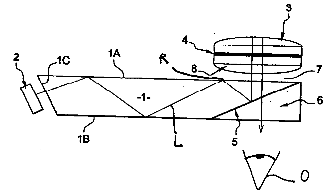
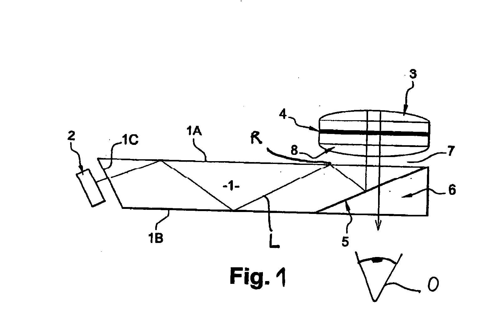
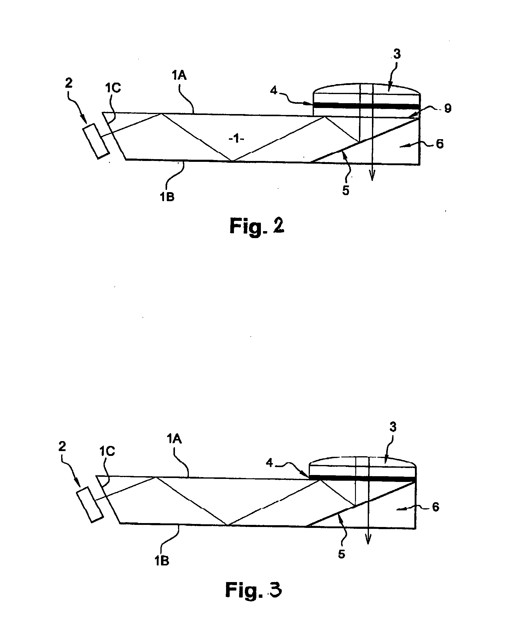
[0032]An optical imager of the invention includes a waveguide 1 having a front face 1A and a rear face 1B and into which light beams emitted by an optical element of a light-beam generator system are introduced via an inlet surface 1C and are directed towards the eye O of the wearer through the rear face 1B by means of an optical arrangement, so as to make it possible to view information content.

[0033]In this embodiment, the front and rear faces 1A and 1B of the waveguide are used in reflection, and a miniature screen 2 constituting the optical element of the light-beam generator system and emitting the light beams towards the imager is disposed in such a manner that the light beams are reflected a plurality of times between the reflective front and rear faces 1A and 1B between said beams being introduced into and leaving the imager.

[0034]The faces are used either with total internal reflection or with reflection that ...


PUM


Abstract

The invention relates to an optical imager including a waveguide having a front face and a rear face and into which light beams emitted by an optical element of a light-beam generator system are introduced via an inlet surface and are directed towards the eye of the wearer through said rear face by means of an optical arrangement, so as to make it possible to view information content, said front and rear faces of the waveguide presenting a property of angular selectivity in reflectance and transmittance, and said optical arrangement comprising a Mangin mirror and a quarterwave plate between said front face and said mirror. In the invention, said quarterwave plate is encapsulated between said mirror and another element.

Description

[0001]The present invention relates to an optical imager for producing an optical display and for making it possible to project information of the image or multimedia type. In particular, it can be positioned on an eyeglass frame.BACKGROUND OF THE INVENTION[0002]Such an information display makes it possible to view multimedia content coming from a mobile telephone, an MP4 or DVD player, a personal computer, a game console, or any other device that enables multimedia content to be supplied.[0003]It is known from U.S. Pat. No. 6,204,974 to make such an imager. Such an optical imager is for shaping the light beams coming from an electronic and optical light-beam generator system of the miniature screen, laser diode, or light-emitting diode type, for generating light beams from an electronic signal. The optical imager directs the light beams towards the eye of the wearer so as to make it possible to view the information content.[0004]That known optical imager is made up of a waveguide h...

Claims


Application Information

Patent Timeline
IPC IPC(8): G02B27/01
CPCG02B5/08G02B5/30G02B27/0101G02B6/00G02B5/3033
Inventor MOLITON, RENAUDBONAFOS, CECILE
Owner ESSILOR INT CIE GEN DOPTIQUE
Learn More