
Light guiding structure and manufacturing of the same

a technology of light guiding and manufacturing, applied in the direction of manufacturing tools, machines/engines, instruments, etc., can solve the problems of bringing the production cost higher, consuming a large amount of led electricity, and comparatively more expensive costs, so as to improve the illumination of a portable device

Inactive Publication Date: 2009-03-05
LIN TAI YEN
View PDF9 Cites 55 Cited by
  • Summary
  • Abstract
  • Description
  • Claims
  • Application Information

AI Technical Summary

Benefits of technology

[0008]In light of the drawbacks of the above prior arts, the primary object of the present invention is to provide a light guiding system for improving illumination of a portable device with a keying unit.

Problems solved by technology

However, because of the need to use multiple LED for the light-guiding plate in this patent, the cost is comparatively more expensive, and the LED consumes a large amount of electricity as well.
Moreover, the addition of convex lens requires relatively more processing procedures during the production, which brings the production cost higher as a result.
On the other hand, by arranging the light source underneath the light-guiding plate, the overall thickness of the resulted device is increased as well, and hence impeding the miniaturization of the device.
Additionally, because U.S. Pat. No. 5,083,240 has to form groove-like reflectors around the perimeter of the light guide plate and to cut corners for reflecting some of the light, such light guiding plate is hard to fabricate.
It can only be fitted to one specific model, but can hardly be applied to other devices, thereby complicating the fabrication process, increasing cost of production, and narrowing down its scope of industrial applications and utilization.
Moreover, as the light is emitted directly from the underneath light source, the type of lighting method employed by U.S. Pat. No. 5,083,240 is a type of directed-lighting, which is also a major cause of Hot Spot effect and over-lighting.
In the prior arts, problems like the failure of light emission, uneven illumination, complicated structure, difficulty in production, higher cost, and difficulty in application by the industry still exist.
Solutions to these problems have been long sought but prior developments have not taught or suggested any solutions, and thus solutions to these problems have long eluded those skilled in the art.

Method used


Image

  • Light guiding structure and manufacturing of the same
  • Light guiding structure and manufacturing of the same
  • Light guiding structure and manufacturing of the same

Examples


first embodiment

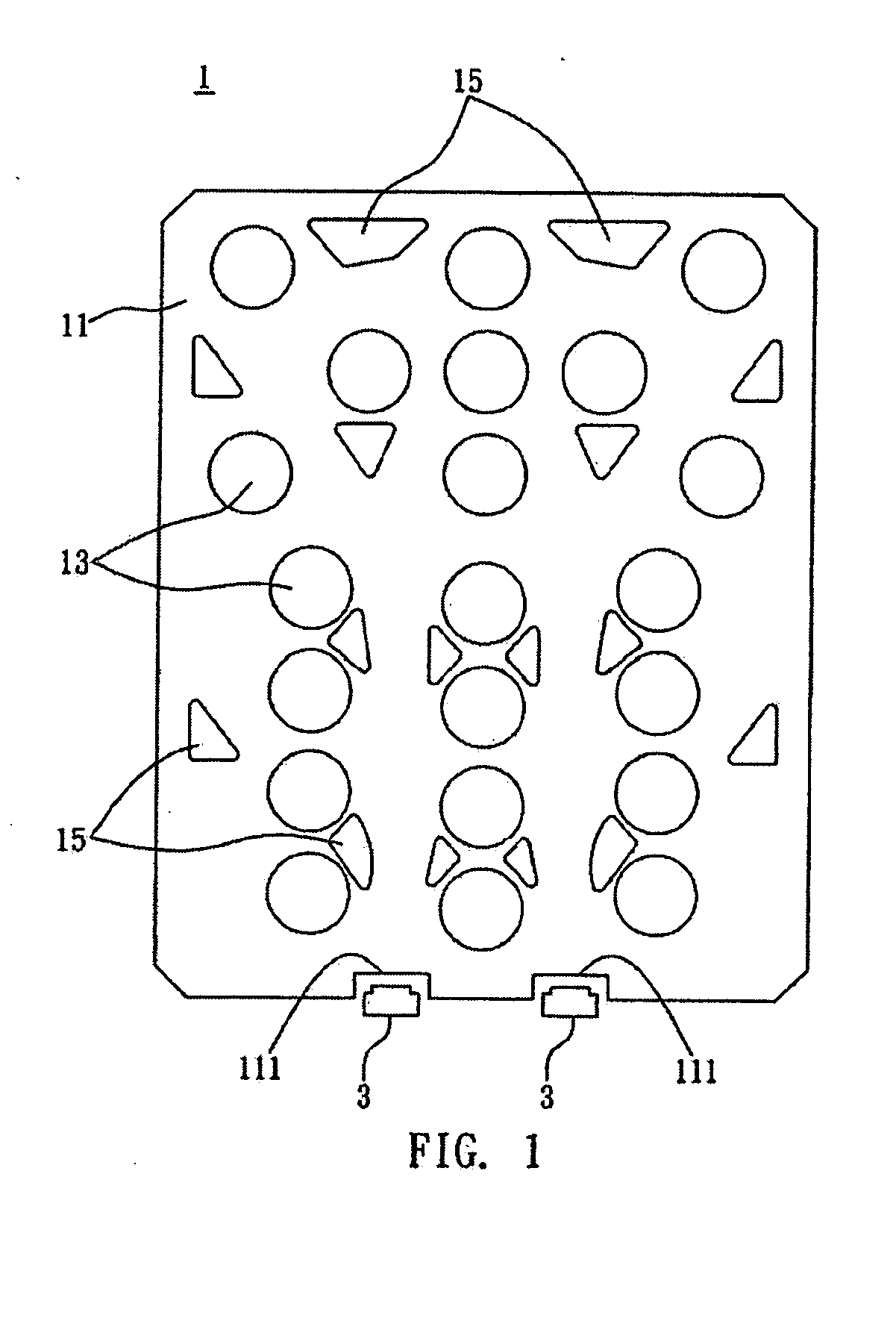
[0037]In a first embodiment, as shown in FIG. 1, the light guiding system 1 may be installed in a portable device having a plurality of keying units (not shown) and a plurality of illuminators 3, such that incident light produced by the illuminators 3 can be transmitted and distributed to each keying unit by the use of the light guiding system 1. Furthermore, the keying units may be exposed from a side of a casing of the portable device. In this embodiment, the light guiding system 1 comprises a light guiding structure 11; a plurality of coupling portions 13 on the light guiding structure for coupling with corresponding keying units; at least an incident portion 111 for receiving incident light produced by the illuminator 3; and a plurality of light guiding portions 15 for guiding the incident light to each coupling portion 13.

[0038]The light guiding structure 11 of the light guiding system 1 may have a top surface, a bottom surface and lateral surfaces. Furthermore, the lateral sur...

second embodiment

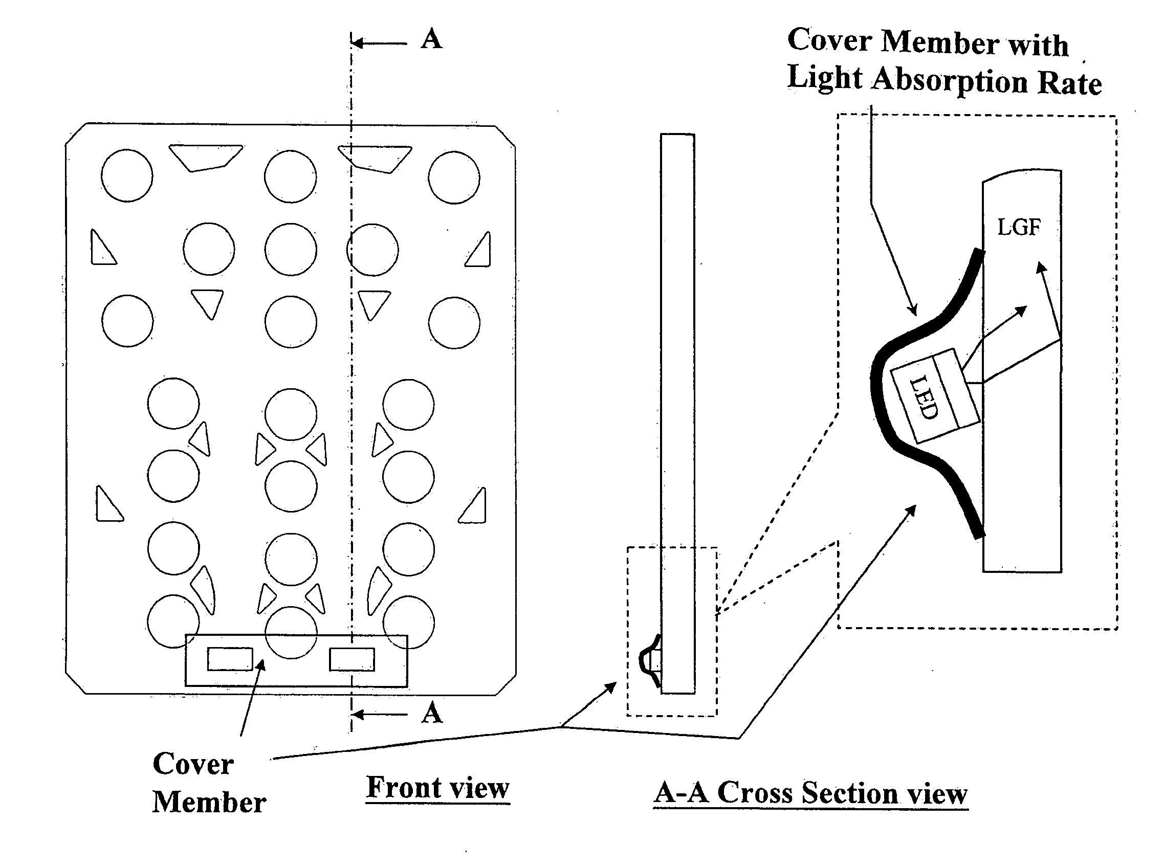
[0049]FIG. 3 and FIGS. 4A to 4B are schematic views depicting the light guiding system 1 in accordance with a second preferred embodiment of the present invention. Most of the structure of the light guiding system 1 of the second preferred embodiment is similar to that of the first preferred embodiment; however, the light guiding system 1 of the second preferred embodiment further comprises a cover member 113.

[0050]In this embodiment, the cover member 113 is placed on the light guiding structure 11 at a location above a side of the incident portion 111 corresponding to the illuminator 3. Furthermore, the cover member 113 may be made of a material selected from the group consisting of gum, rubber, glass, plastics, (poly)silicone, (poly)silane, polycarbonate (PC), polymethyl (meth)acrylate (PPMA), polystyrene (PS), polyamide (PA), methyl(meth)acrylate-styrene (MS), polybutylene terephthalate (PBT), polyethylene terephthalate (PET), polypropylene (PP), polyvinyl chloride (PVC), acrylon...

third embodiment

[0054]FIGS. 5A to 5F are schematic views depicting a light guiding system 1 in accordance with a third preferred embodiment of the present invention. Most of the structure of the light guiding system 1 of the third preferred embodiment is similar to that of the first preferred embodiment; however, the light guiding system 1 of the third preferred embodiment may be equipped with direct lighting (referring to the illuminator 3′ as shown in FIGS. 5A to 5D), equipped with direct and side lighting, or equipped with tilted lighting.

[0055]Referring to FIG. 5A, an incident portion 111′ of the light guiding system 1 is formed on the bottom surface of the light guiding structure 11 at a location corresponding to an illuminator 3′ such as an LED. Arrangement as such may be applied to a particular area required a high intensity of illumination. Furthermore, if the light guiding system 1 is equipped with the direct lighting as well as the side lighting (referring to the illuminator 3 as shown in...


PUM

PropertyMeasurementUnit
Thicknessaaaaaaaaaa
Thicknessaaaaaaaaaa
Thicknessaaaaaaaaaa

Abstract

The present invention discloses a light guiding system, applied to a portable device configured with at least a keying unit; an illuminator producing incident light to illuminate said portable device. The light guiding system comprising: a light guiding structure; at least an incident portion provided on a side of the light guiding structure to receive the incident light from the illuminator; a plurality of light guiding portions to guide the incident light to the at least one keying unit; and a chemical layer provided on the light guiding structure.

Description

CROSS-REFERENCE TO RELATED APPLICATIONS[0001]This application is related to and claims priority to U.S. provisional patent application, U.S. Provisional Application No. 60 / 927,962, filed on May 8, 2007, by the applicant Tai-Yen Lin, entitled “Light Guiding Structure And Manufacturing Of The Same.”FIELD OF THE INVENTION[0002]The present invention relates to a light guiding system; more particularly, the present invention relates to a light guiding system applied to a portable or handheld device equipped with at least a keying unit and at least an illuminator.BACKGROUND OF THE INVENTION[0003]Nowadays, portable or handheld electronic devices from the video conferencing sector, information sector, communication sector, home appliance sector, and consumer section; such as mp3 players, cell phone, personal digital assistant (PDA), and remote controller, have become an indispensable part of our daily life, but sometimes the need to use the devices in occasions without sufficient lighting h...

Claims


Application Information

Patent Timeline
IPC IPC(8): G01D11/28C03B37/022B29C48/08B29C48/09
CPCB29C47/0021B29C47/0023G02B6/0073G02B6/0021G02B6/0068B29C47/884B29C48/08B29C48/09B29C48/9135B29C48/906
Inventor LIN, TAI-YEN
Owner LIN TAI YEN
Features
  • Generate Ideas
  • Intellectual Property
  • Life Sciences
  • Materials
  • Tech Scout
  • Unparalleled Data Quality
  • Higher Quality Content
  • 60% Fewer Hallucinations
Learn More