Multi-part cast turbine engine component having an internal cooling channel and method of forming a multi-part cast turbine engine component

Inactive Publication Date: 2009-03-05
GENERAL ELECTRIC CO
View PDF14 Cites 14 Cited by
  • Summary
  • Abstract
  • Description
  • Claims
  • Application Information

AI Technical Summary

Problems solved by technology

In either case, the passages are difficult to manufacture, expensive, and limited in shape.
In addition, ceramic cores can react negatively with various alloys used in creating the blades.
Moreover, ceramic cores are fragile and prone t

Method used


Image

  • Multi-part cast turbine engine component having an internal cooling channel and method of forming a multi-part cast turbine engine component
  • Multi-part cast turbine engine component having an internal cooling channel and method of forming a multi-part cast turbine engine component
  • Multi-part cast turbine engine component having an internal cooling channel and method of forming a multi-part cast turbine engine component

Examples


Embodiment Construction

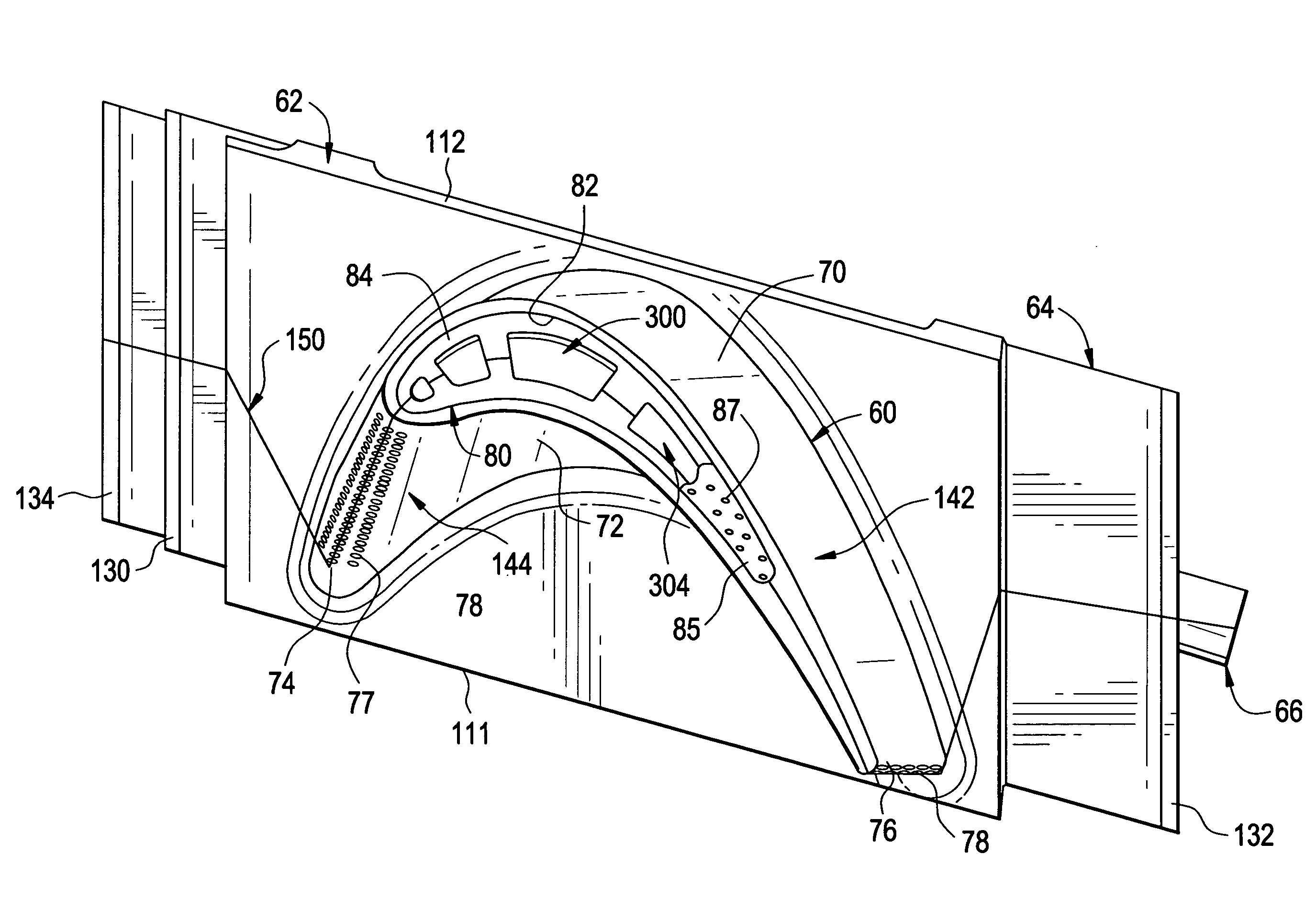
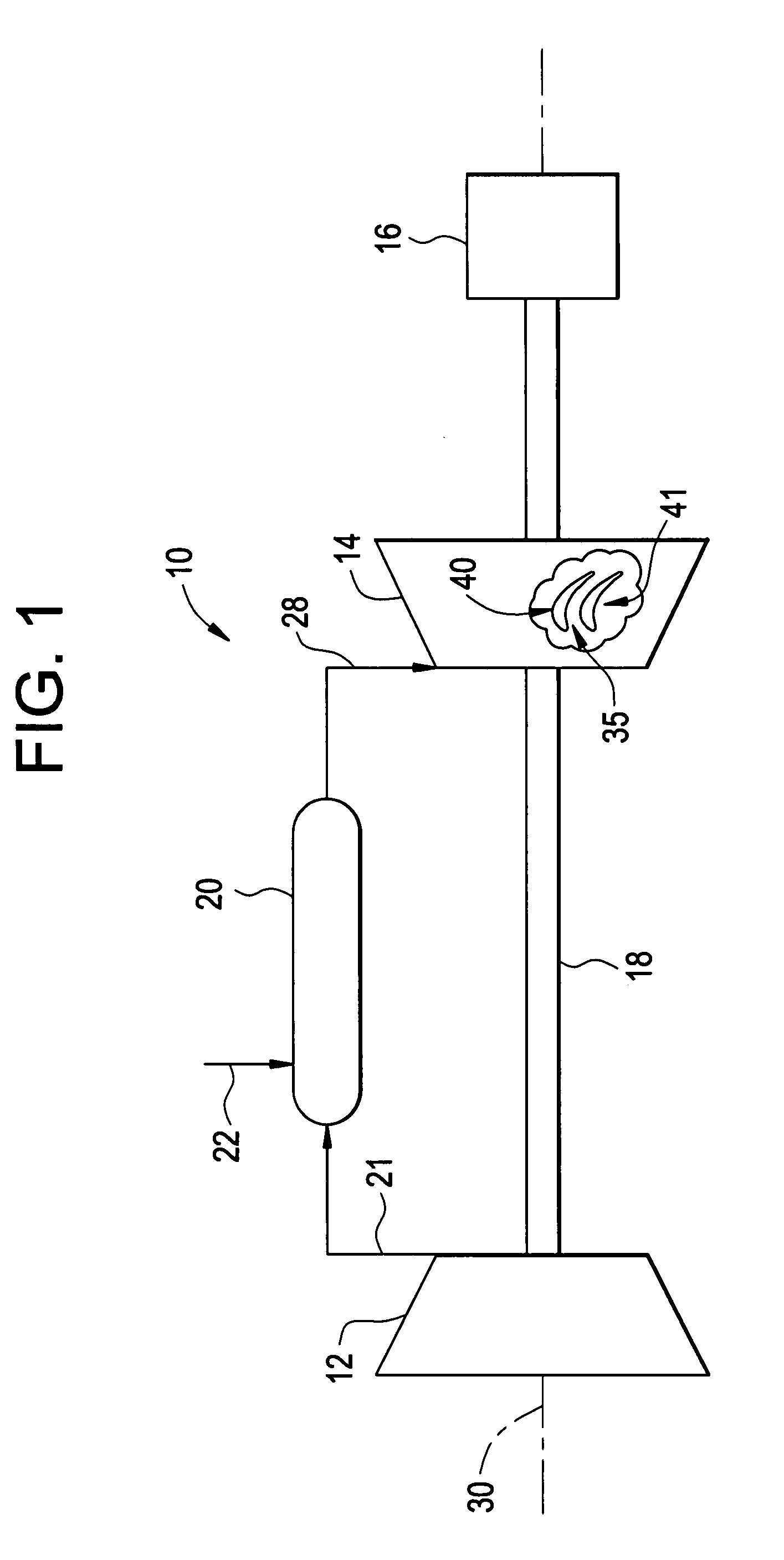
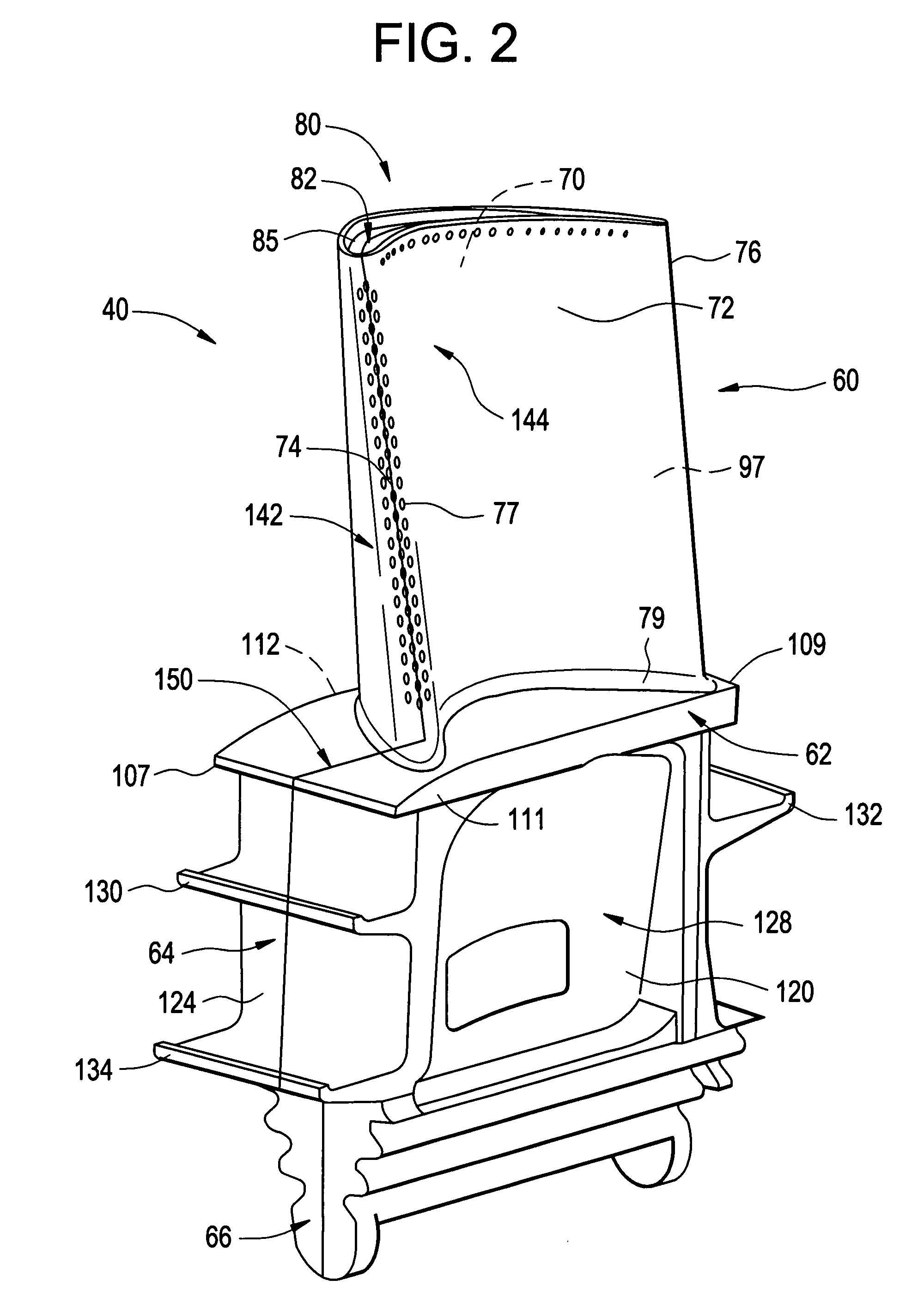
[0011]With initial reference to FIG. 1, a gas turbine engine constructed in accordance with the present invention is generally indicated at 10. Turbine engine 10 includes a compressor 12 operatively coupled to a turbine 14 and an electrical generator16 via a shaft 18. Shaft 18 is illustrated as a single, monolithic component, however, it should be readily understood that shaft 18 could also be formed in multiple segments with each segment being coupled to an adjacent engine component.

[0012]In any event, engine 10 is further shown to include a combustor 20 in which air 21 from compressor 12 and a fuel 22 are mixed to form a combustible mixture. The combustible mixture is ignited to form a high pressure, high temperature combustion product or gas 28 that is used to drive turbine 14. More specifically, high pressure, high temperature gas 28 enters into turbine 14 and impinges upon a rotor assembly 35 having a plurality of rotor blades, two of which are indicated at 40 and 41. Rotor ass...


PUM

PropertyMeasurementUnit
Fractionaaaaaaaaaa

Abstract

A multi-part cast component for a turbine engine includes a first component section having a main body portion including at least one cooling flow passage section, and a second component section having a main body including at least one cooling flow passage section. The first and second component sections are joined along a parting line to form a turbine engine component with the at least one cooling flow passage section of the first component section aligning with the at least one cooling flow passage of the second component section to form a cooling flow channel.

Description

BACKGROUND OF THE INVENTION[0001]The present invention pertains to the art of turbine engines and, more particularly, to a two part cast turbine engine component having internally formed cooling cavities.[0002]In general, gas turbine engines combust a fuel / air mixture to release heat energy in the form of a high temperature gas stream that is channeled to a turbine section via a hot gas path. More specifically, a compressor compresses incoming air to a high pressure. The high pressure air is delivered to a combustion chamber to mix with fuel and form a combustible mixture. The combustible mixture is then ignited to form a high pressure, high velocity gas stream which is delivered to the turbine. The high pressure air impacts upon rotor blades or buckets that form part of a turbine rotor assembly. In this manner, the turbine converts thermal energy from the high temperature, high velocity gas stream to mechanical energy that rotates a turbine shaft.[0003]In many cases, a cooling gas ...

Claims


Application Information

Patent Timeline
IPC IPC(8): F01D5/14
CPCF01D5/187Y10T29/49341F05D2230/23F05D2230/211
Inventor MOORS, THOMAS
Owner GENERAL ELECTRIC CO
Why Eureka
Try Eureka