Oriented fiber ceramic matrix composite abradable thermal barrier coating

a technology of oriented fiber ceramics and composites, applied in wind motors with parallel air flow, wind motors with perpendicular air flow, liquid fuel engine components, etc., can solve the problems of increasing the clearance between the outer air seal and the blade tips, the vulnerability of the coating to erosion and spalling, and the damage of the coating

Active Publication Date: 2009-03-05
RAYTHEON TECH CORP
View PDF18 Cites 22 Cited by
  • Summary
  • Abstract
  • Description
  • Claims
  • Application Information

AI Technical Summary

Problems solved by technology

One drawback of the abradable ceramic coating is its vulnerability to erosion and spalling.
Loss of the coating increases clearance between the outer air seal and the blade tips and is detrimental to turbine engine efficiency and/or the durability ...

Method used


Image

  • Oriented fiber ceramic matrix composite abradable thermal barrier coating
  • Oriented fiber ceramic matrix composite abradable thermal barrier coating
  • Oriented fiber ceramic matrix composite abradable thermal barrier coating

Examples


Embodiment Construction

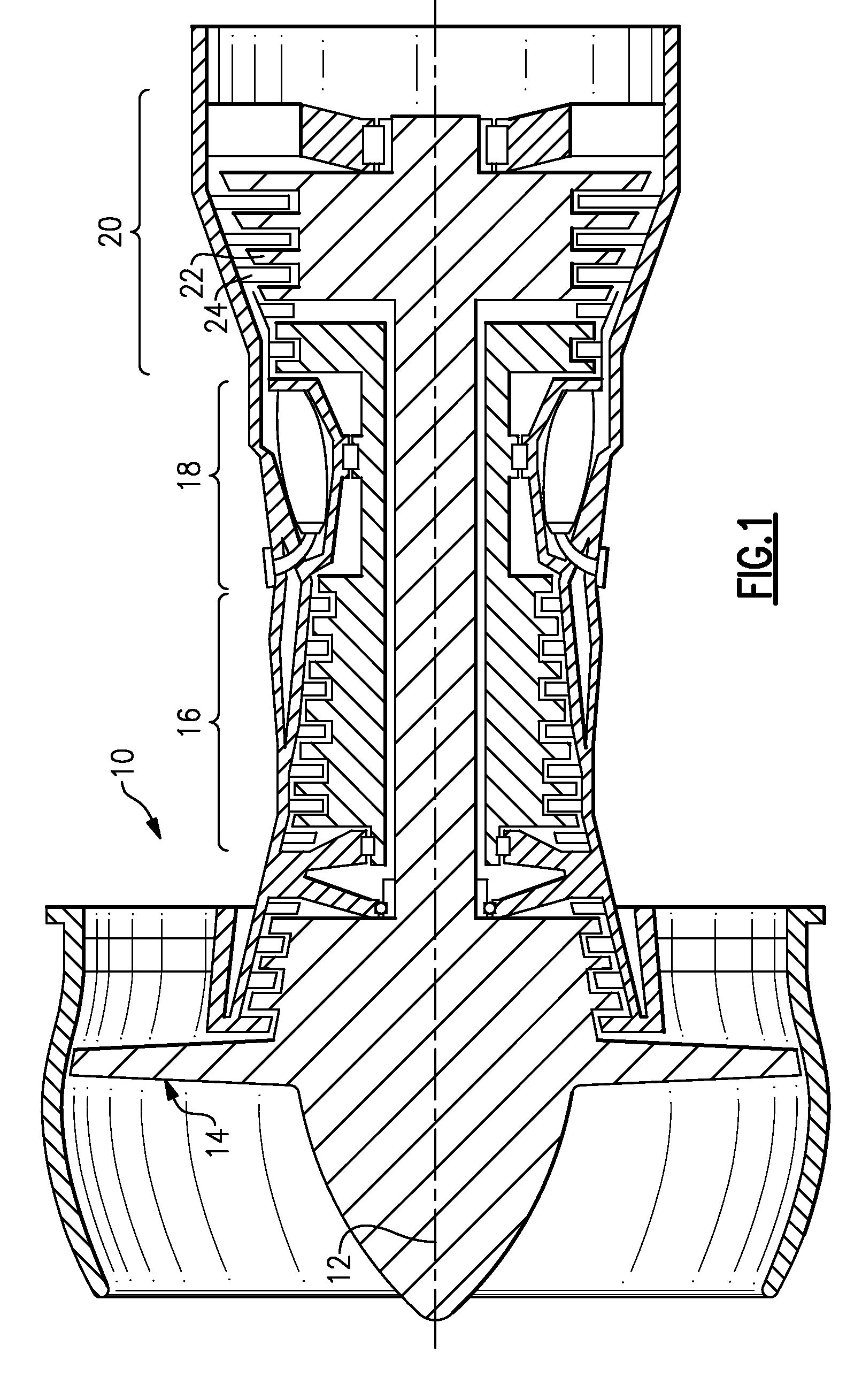
[0014]FIG. 1 illustrates selected portions of an example gas turbine engine 10, such as a gas turbine engine 10 used for propulsion. In this example, the gas turbine engine 10 is circumferentially disposed about an engine centerline 12. The engine 10 includes a fan 14, a compressor section 16, a combustion section 18 and a turbine section 20 that includes turbine blades 22 and turbine vanes 24. As is known, air compressed in the compressor section 16 is mixed with fuel and burned in the combustion section 18 to produce hot gases that are expanded in the turbine section 20. FIG. 1 is a somewhat schematic presentation for illustrative purposes only and is not a limitation on the disclosed examples. Additionally, there are various types of gas turbine engines, many of which could benefit from the examples disclosed herein, which are not limited to the design shown.

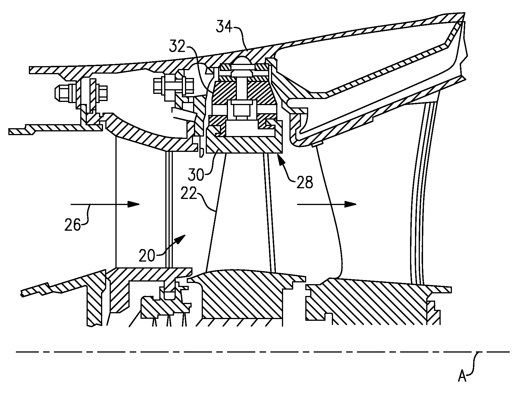
[0015]FIG. 2 illustrates selected portions of the turbine section 20. The turbine blade 22 receives a hot gas flow 26 from ...


PUM

PropertyMeasurementUnit
Fractionaaaaaaaaaa
Fractionaaaaaaaaaa
Fractionaaaaaaaaaa

Abstract

A method of manufacturing a gas turbine engine component includes the steps of forming a ceramic workpiece having oriented ceramic reinforcement, and severing the ceramic workpiece to produce a ceramic member having a desired orientation of the ceramic reinforcement. The ceramic member is then attached to a turbine engine component as a thermal barrier layer for the turbine engine component.

Description

BACKGROUND OF THE INVENTION[0001]The government may have certain rights in this invention pursuant to Contract No. F33615-03-D-2354 awarded by the United States Air Force.[0002]This invention relates to protective thermal barrier layers and, more particularly, to abradable ceramic thermal barrier layers and methods of manufacture.[0003]Components that are exposed to high temperatures, such as a component within a gas turbine engine, typically include protective coatings. For example, turbine blades, turbine vanes, and blade outer air seals typically include one or more coating layers that protect the component from erosion, oxidation, corrosion or the like to thereby enhance durability and / or maintain efficient operation of the engine. In particular, conventional outer air seals include an abradable ceramic coating that contacts tips of the turbine blades during engine operation such that the blades abrade the coating upon operation of the engine. The abrasion between the coating an...

Claims


Application Information

Patent Timeline
IPC IPC(8): F01D5/28B23P15/04B32B15/04
CPCF01D11/125Y10T29/4932Y02T50/672B32B18/00C04B37/001C04B37/006C04B37/021C04B37/026C04B2235/522C04B2235/5236C04B2235/5268C04B2237/123C04B2237/125C04B2237/126C04B2237/341C04B2237/343C04B2237/348C04B2237/38C04B2237/405C04B2237/406F05D2230/90F05D2300/603F05D2300/611F05D2300/614F05D2300/2118F05D2300/2112C04B2237/32Y10T29/49321Y10T29/49323Y10T428/12618Y10T428/12611Y02T50/67Y02T50/60
Inventor STROCK, CHRISTOPHER W.THOLEN, SUSAN M.
Owner RAYTHEON TECH CORP
Why Eureka
Try Eureka