Storage system and power consumption reduction method for the same

a technology of storage system and power consumption reduction, which is applied in the direction of liquid/fluent solid measurement, micro-instruction address formation, instruments, etc., can solve the problems of unnecessary disks, increased power consumption in the entire disk array, and inability to achieve efficient disk operation control, etc., to achieve maximum data capacity efficiency and power-saving

Active Publication Date: 2009-03-05
HITACHI LTD
View PDF2 Cites 50 Cited by
  • Summary
  • Abstract
  • Description
  • Claims
  • Application Information

AI Technical Summary

Benefits of technology

[0010]According to the invention, it is possible to maximize the data capacity efficiency and power-saving effect when the data de-duplication and disk operation control are performed at the same time.

Problems solved by technology

Operating these disks at the same time increases the power consumption in the entire disk array.
Accordingly, even if disk arrays performing data de-duplication try to reduce power consumption by limiting the number of active disks, efficient disk operation control cannot be achieved because they have been designed with no consideration given to the disk access required in the de-duplication.
Accordingly, unnecessary disks operate and an optimal power-saving effect cannot be produced.

Method used


Image

  • Storage system and power consumption reduction method for the same
  • Storage system and power consumption reduction method for the same
  • Storage system and power consumption reduction method for the same

Examples


embodiment 1

(1-1) Configuration

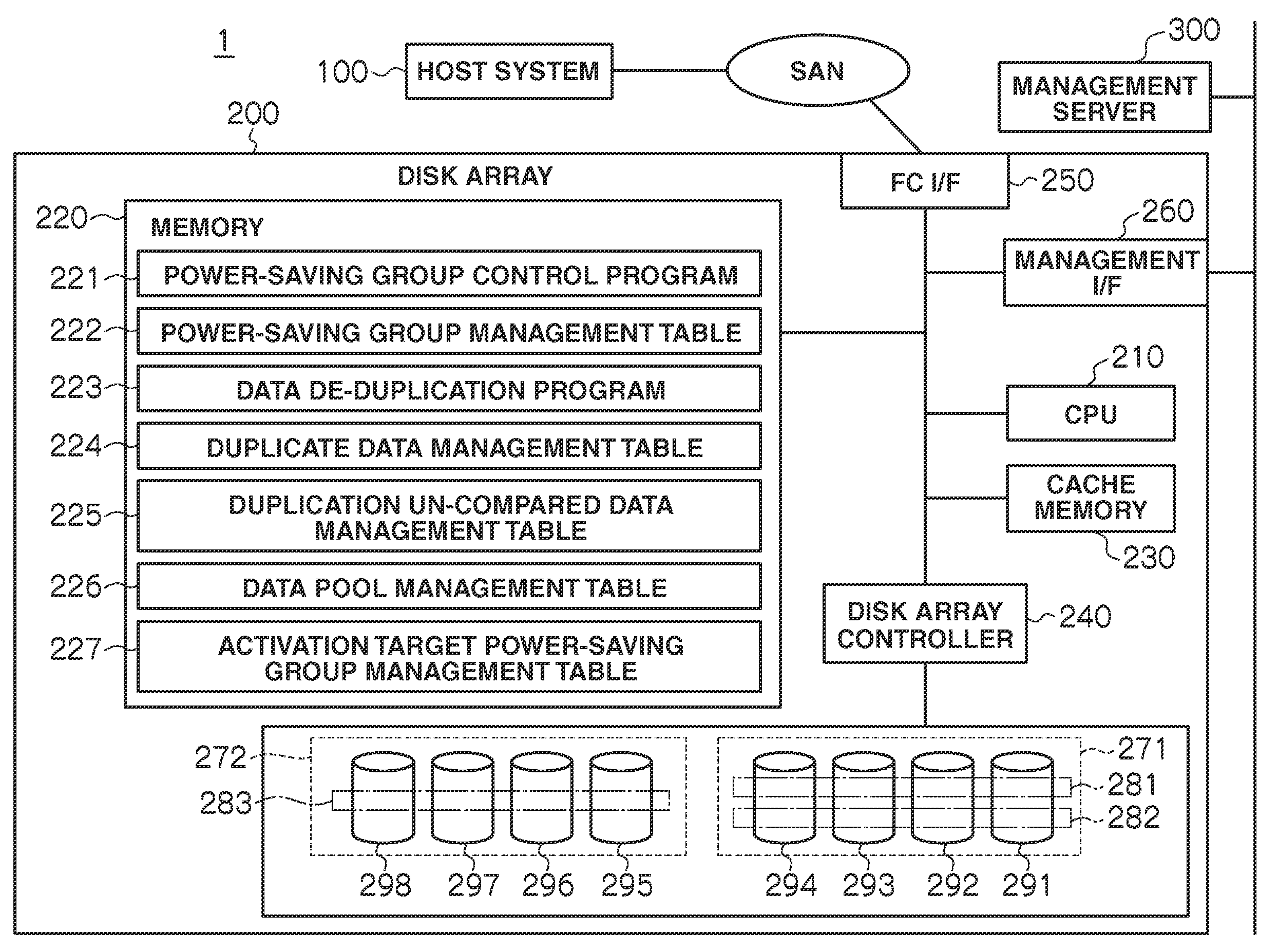
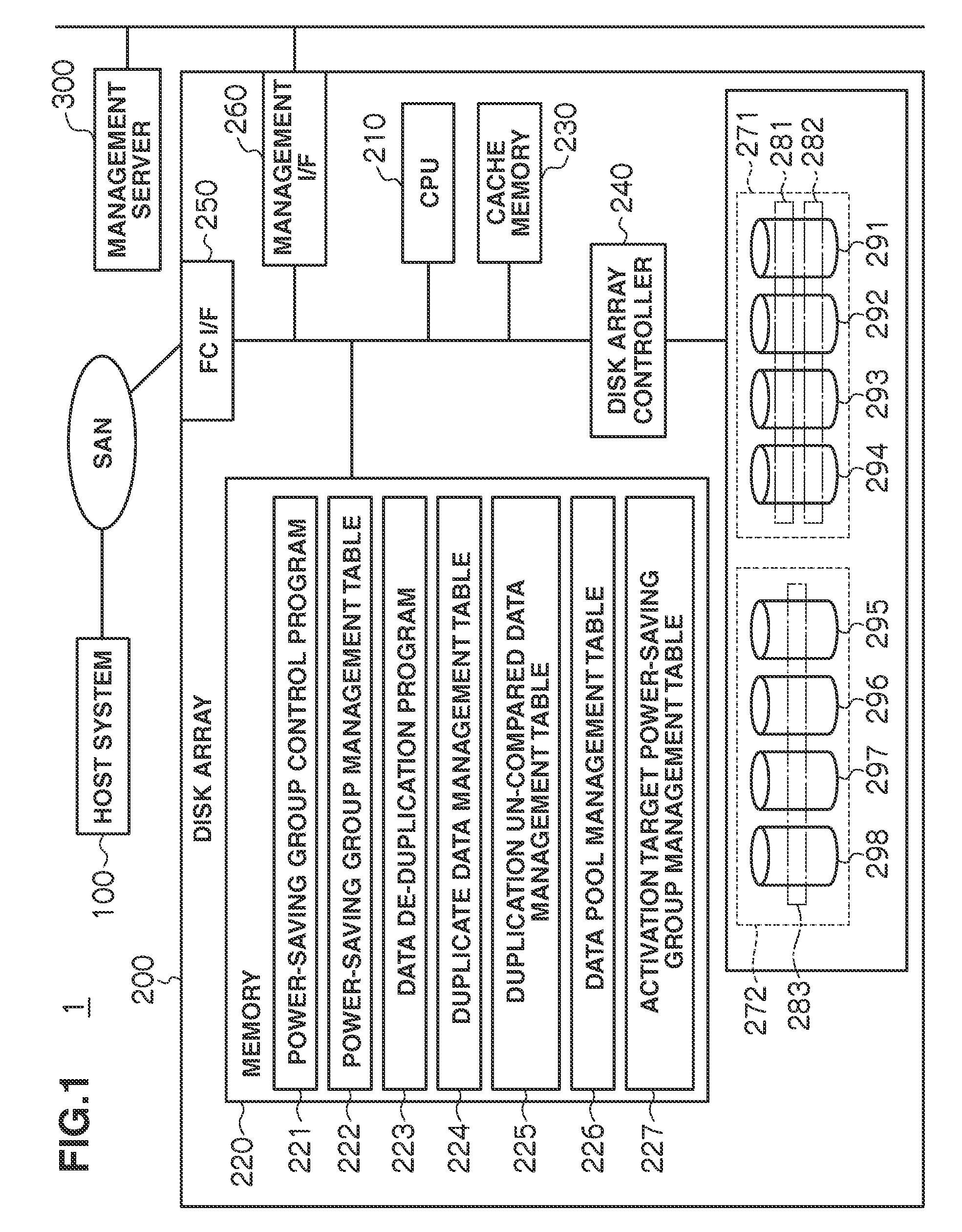
[0026]FIG. 1 shows an example of the configuration of a storage system 1. In FIG. 1, a host system 100—a computer with an application program for business or similar running—and a disk array 200 storing data transmitted from the host system 100 are connected to each other via a SAN (Storage Area Network). Note that although FIG. 1 shows only one host system 100 as a computer in FIG. 1, there may be more than one computer in practice.

[0027]The disk array 200 has a Fibre Channel interface (“FC I / F”) 250 connected to the SAN, and a management interface (“management I / F”) 260. Note that the management I / F 260 is used when sending / receiving the data in the disk array 200 to / from other apparatuses such as a management server 300. The FC I / F 250 is used when sending the data written in the disk array 200 to the host system 100 or receiving the data to be written in the disk array from the host system 100.

[0028]The disk array 200 also has a CPU 210 for controlling the dis...

embodiment 2

(2-1) Configuration

[0118]The configuration of a storage system in Embodiment 2 is the same as that of the storage system 1 in Embodiment 1 so explanations will be omitted.

(2-2) Power Consumption Reduction in Disk Array

[0119]Power consumption reduction in Embodiment 2 is the same as that in Embodiment 1 so explanations will be omitted. However, in Embodiment 2, of the power-saving groups, one or more power-saving groups (“permanently-active groups”) are defined as groups that are always active and so accessible while the disk array 200 is in operation.

(2-3) Data De-Duplication

[0120]Data de-duplication in Embodiment 2 is the same as that in Embodiment 1, so explanations will be omitted.

(2-4) Power Saving Control Involving Data De-Duplication

[0121]Power saving control in Embodiment 2 is the same as that in Embodiment 1 except for the points below, so explanations will be given only for the differences.

[0122]Unlike Embodiment 1, in Embodiment 2, the above permanently-active groups are u...

embodiment 3

(3-1) Configuration

[0126]The configuration of a storage system in Embodiment 3 is the same as that in Embodiment 1, so explanations will be omitted.

(3-2) Power Consumption Reduction in Disk Array

[0127]Power consumption reduction in Embodiment 3 is the same as that in Embodiment 1 so explanations will be omitted.

(3-3) Data De-Duplication

[0128]Data de-duplication in Embodiment 3 is the same as that in Embodiment 1 so detail explanations will be omitted. However, in Embodiment 3, the data de-duplication program 223 divides the write data the host system 100 sends to the disk array 200 into segments and calculates hash values for those segments. The size of the segments may differ according to the specifications for the data de-duplication.

(3-4) Data De-Duplication Involving Power Saving Control

[0129]Explanations will be given below only to the differences from Embodiment 1.

[0130]Unlike Embodiment 1, in Embodiment 3, write data is divided into segments. The host system 100 recognizes th...


PUM


Abstract

This invention achieves data capacity efficiency via data de-duplication and maximizes a power-saving effect by disk operation control. In a storage system, when data is received from a computer, a value representing the bit string for the data is calculated and whether or not a value identical to the calculated value is stored in a data management table is judged. If it is judged that an identical value is not stored, the received data is registered in the data management table and stored, based on a group management table, in disk device(s) associated with a logical unit number of a logical unit constituting an active group. Meanwhile, if it is judged that an identical value is stored, the received data is stored in disk device(s) based on the group information managed in the group management table and the management information managed in the data management table.

Description

CROSS-REFERENCES TO RELATED APPLICATIONS[0001]This application relates to and claims priority from Japanese Patent Application No. 2007-224743, filed on Aug. 30, 2007, the entire disclosure of which is incorporated herein by reference.BACKGROUND[0002]1. Field of the Invention[0003]The present invention relates to a storage system and a power consumption reduction method for the storage system, and is suitable for use in a storage system using disks and a power consumption reduction method for the storage system.[0004]2. Description of Related Art[0005]In relation to the backup and archival of business data, a data de-duplication technique (hereinafter sometimes called “data de-duplication”) has been suggested, with which data will not be stored in disks redundantly to avoid unnecessary increase in the amount of data in disk arrays and improve the efficiency of the data capacity. With the data de-duplication technique, when the content of new data to be written in the disks, i.e., so...

Claims


Application Information

Patent Timeline
Patent Type & Authority Applications(United States)
IPC IPC(8): G06F1/32G06F12/00
CPCG06F3/0608G06F3/0634G06F3/0689G06F3/0646G06F3/0641
Inventor MORI, HAJIME
Owner HITACHI LTD
Why Eureka
Try Eureka