Communication apparatus, reception method in said apparatus, codec, decoder, communication module, communication unit and decoding method

a communication apparatus and reception method technology, applied in the field of communication apparatuses, can solve problems such as the spread of apparent errors across the entire header, the inability to correct errors, so as to achieve the effect of suppressing the effect of an error operation

Inactive Publication Date: 2009-03-05
CANON KK
View PDF12 Cites 21 Cited by
  • Summary
  • Abstract
  • Description
  • Claims
  • Application Information

AI Technical Summary

Benefits of technology

[0027]Further, a feature object of the present invention is to suppress an affect of an error operation by a descrambler, even in a case where bit error has occurred in a scramble index field contained in first header information of a header.

Problems solved by technology

If an error exceeding a single bit exists, the wireless frame is discarded on the grounds that the number of errors is such that the errors cannot be corrected.
However, in a case where a bit error has occurred in the scramble index field contained in the PHY header, even an error that is one bit at most, a conventional codec will cause the descrambler 201 to operate based upon an improper scramble pattern and, as a result, apparent error spreads over the entire header.
Here bit error has spread across the entire header owing to non-agreement with the scramble pattern.
Since improper descrambling processing is thus executed by a scramble pattern different from that used in scrambling processing at the time of transmission, apparent bit error is enlarged in the scrambler output.
As a result, even if bit error that has occurred in the scramble index field is a single bit that is within the error correction capability of a CRC code, error correction can no longer be performed correctly.
Further, this may bring about erroneous decisions of other types and may lead to a rise in the rate at which wireless frames are lost.

Method used


Image

  • Communication apparatus, reception method in said apparatus, codec, decoder, communication module, communication unit and decoding method
  • Communication apparatus, reception method in said apparatus, codec, decoder, communication module, communication unit and decoding method
  • Communication apparatus, reception method in said apparatus, codec, decoder, communication module, communication unit and decoding method

Examples


Embodiment Construction

[0048]A preferred embodiment of the present invention will now be described in detail with reference to the accompanying drawings. It should be noted that the embodiment below does not limit the present invention set forth in the claims and that not all of the combinations of features described in the embodiment are necessarily essential as means for attaining the objects of the invention.

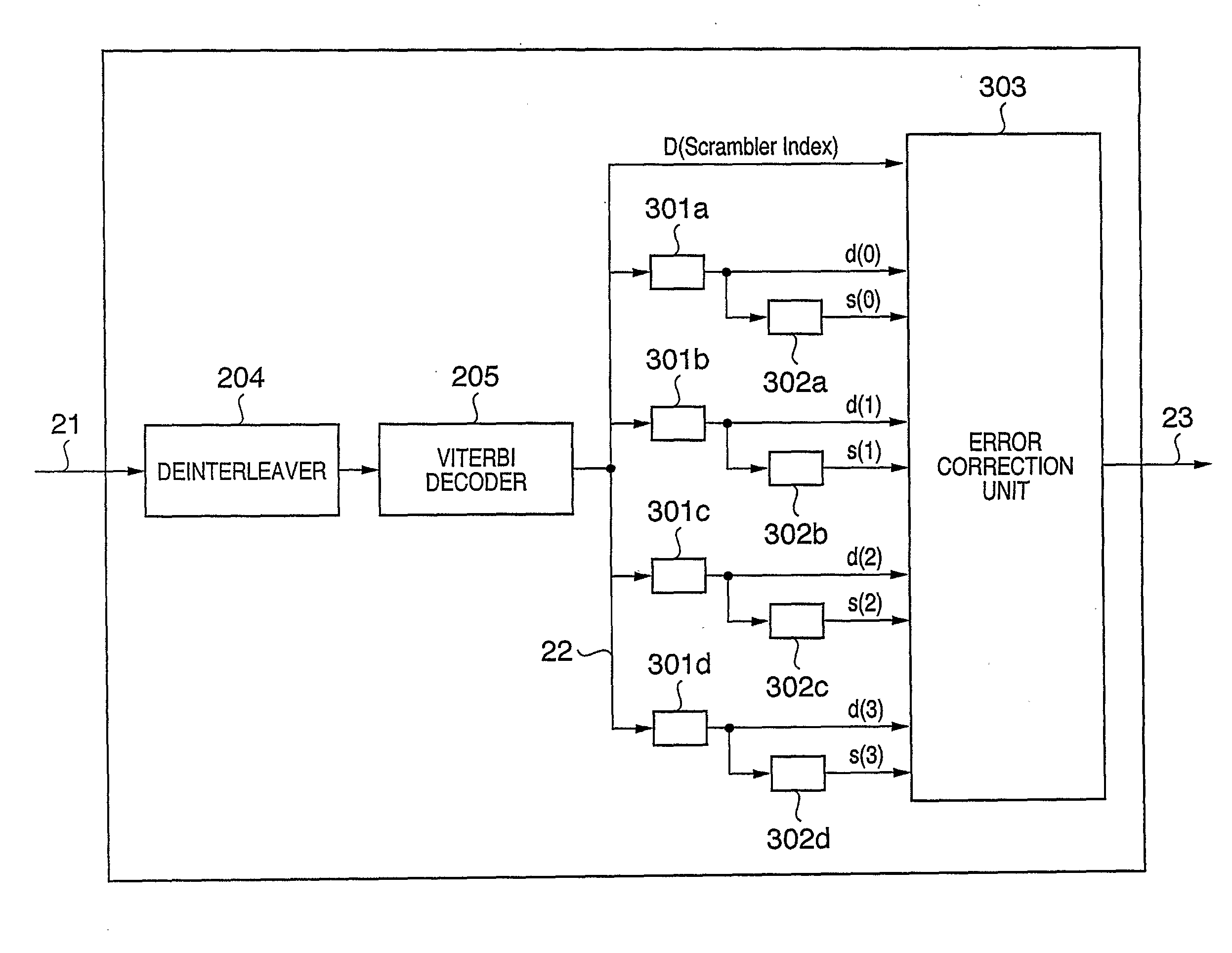
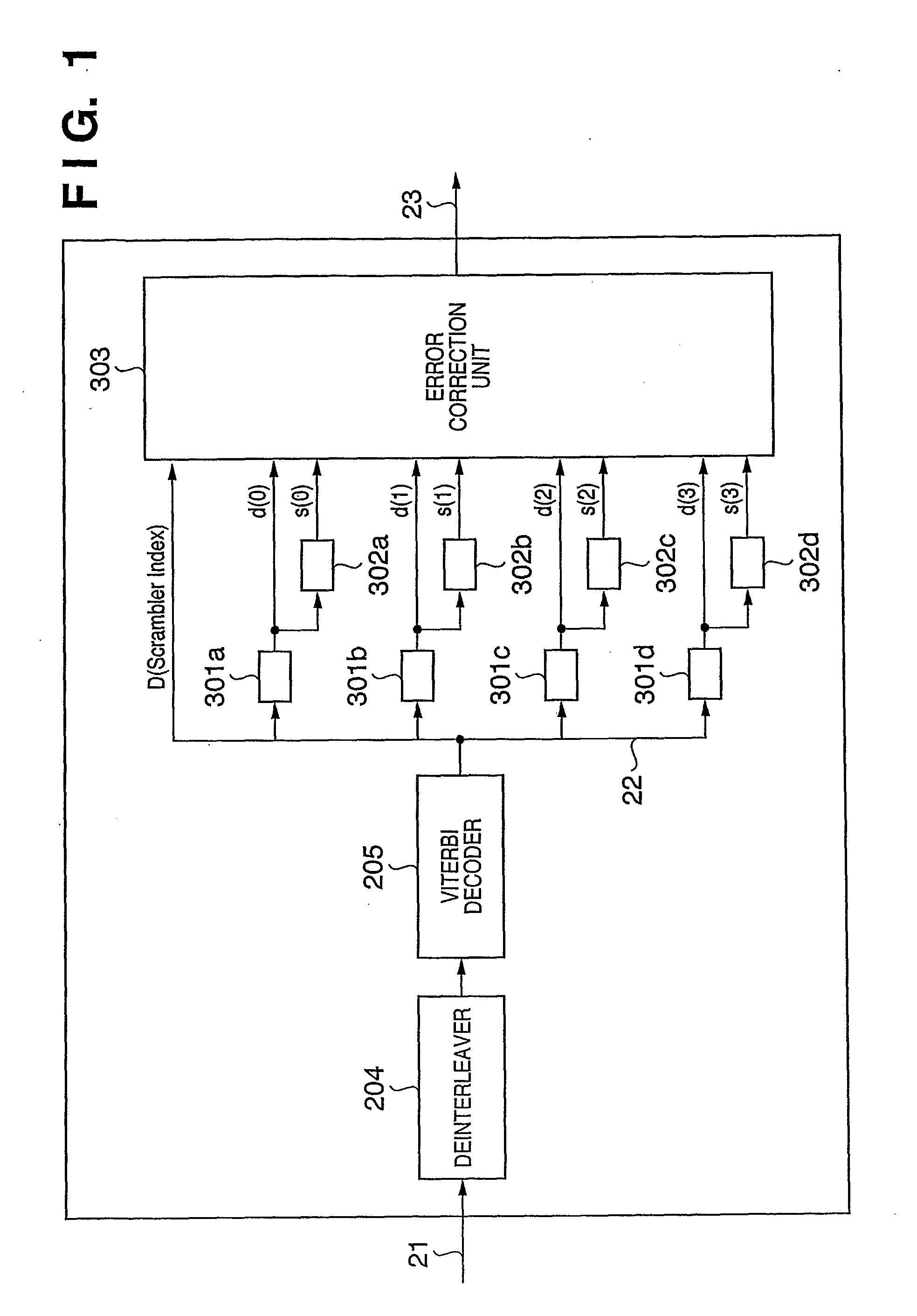
[0049]FIG. 1 is a block diagram for describing the structure of a codec in a wireless communication unit disposed in a receive-side wireless communication apparatus according to an embodiment of the present invention.

[0050]A receive-side codec according to this embodiment accepts demodulated data 21 from a modem (not shown), subjects the demodulated data 21 to deinterleave processing using a deinterleaver 204 and decodes the demodulated data using a Viterbi decoder 205. The decoded data 22 (D in FIG. 1) that is output from the Viterbi decoder 205 is composed of a header and data payload. However, s...


PUM


Abstract

A communication apparatus includes a plurality of descramblers for subjecting a second header portion of a received frame to descrambling processing using pseudo-random sequences that differ from one another; a plurality of syndrome arithmetic units for performing a syndrome calculation, which is in accordance with a cyclic redundancy check code, with respect to headers descrambled by respective ones of the plurality of descramblers, and an error correction unit for selecting a header that has been descrambled by one descrambler among the plurality of descramblers as a receive header, in accordance with syndrome values calculated by respective ones of the plurality of syndrome arithmetic units.

Description

TECHNICAL FIELD[0001]This invention relates to a communication apparatus for performing data communication between devices, a method of reception in this apparatus, a codec, a decoder, a communication module, a communication unit and a decoding method.BACKGROUND ART[0002]At present, the planning of standards is proceeding as the IEEE 802.15 group of standards in relation to WPAN. With regard to network topology and media-access protocols, specifications have already been decided in the IEEE 802.15.3 standard. Furthermore, MBOA specifications and DS-UWB specifications, etc., based on UWB (Ultra-Wide Band) communication schemes have been proposed as high-speed WPAN standards.[0003]FIG. 3 is a diagram illustrating the structure of a wireless frame in a WPAN system proposed in specifications.[0004]As illustrated, the WPAN wireless frame is composed of a header 300 and data payload 301. The header 300 contains information necessary for protocol processing in the PHY or MAC layer. User da...

Claims


Application Information

Patent Timeline
Patent Type & Authority Applications(United States)
IPC IPC(8): H03M13/15G06F11/10
CPCH03M13/09H03M13/11H03M13/3738H03M13/63H04L1/0072H04L1/0054H04L1/0057H04L1/0061H04L1/0045
Inventor KANDA, TETSUOEGUCHI, TADASHI
Owner CANON KK
Why Eureka
Try Eureka