Water leakage monitoring system

a monitoring system and water leakage technology, applied in fluid tightness measurement, instruments, machines/engines, etc., can solve the problems of inability to instantly determine a leakage, inability to comprehensively determine a leakage state in many distribution blocks connected to a main trunk line of public water, etc., to achieve quick and easy estimation of a leakage position

Active Publication Date: 2009-03-12
TOSHIBA INFRASTRUCTURE SYST & SOLUTIONS CORP +1
View PDF4 Cites 52 Cited by
  • Summary
  • Abstract
  • Description
  • Claims
  • Application Information

AI Technical Summary

Benefits of technology

[0029]According to the present invention, there is provided a water leakage monitoring system, which can speedy and easily estimate a water leakage position from a flow rate change of measure...

Problems solved by technology

Therefore, it is impossible to comprehensively determine a leakage state in many distribution blocks connected to a main trunk line of public water.
According to the foregoing two conventional water leakage dete...

Method used


Image

  • Water leakage monitoring system
  • Water leakage monitoring system
  • Water leakage monitoring system

Examples


first embodiment

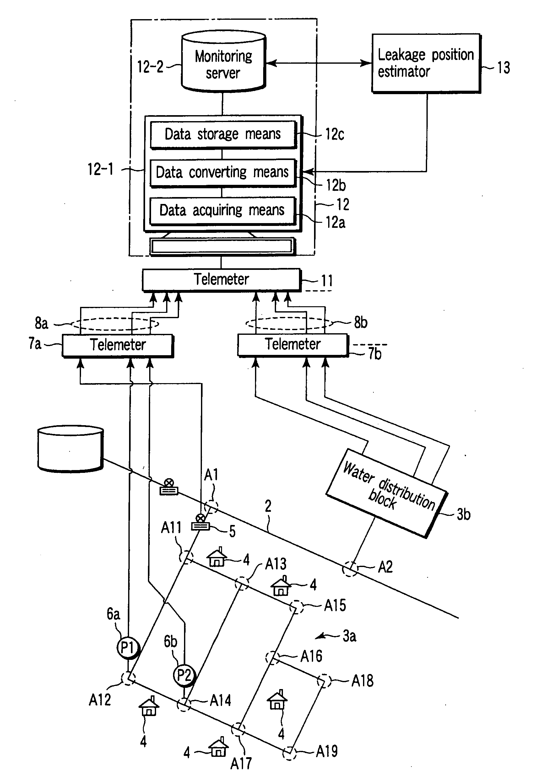
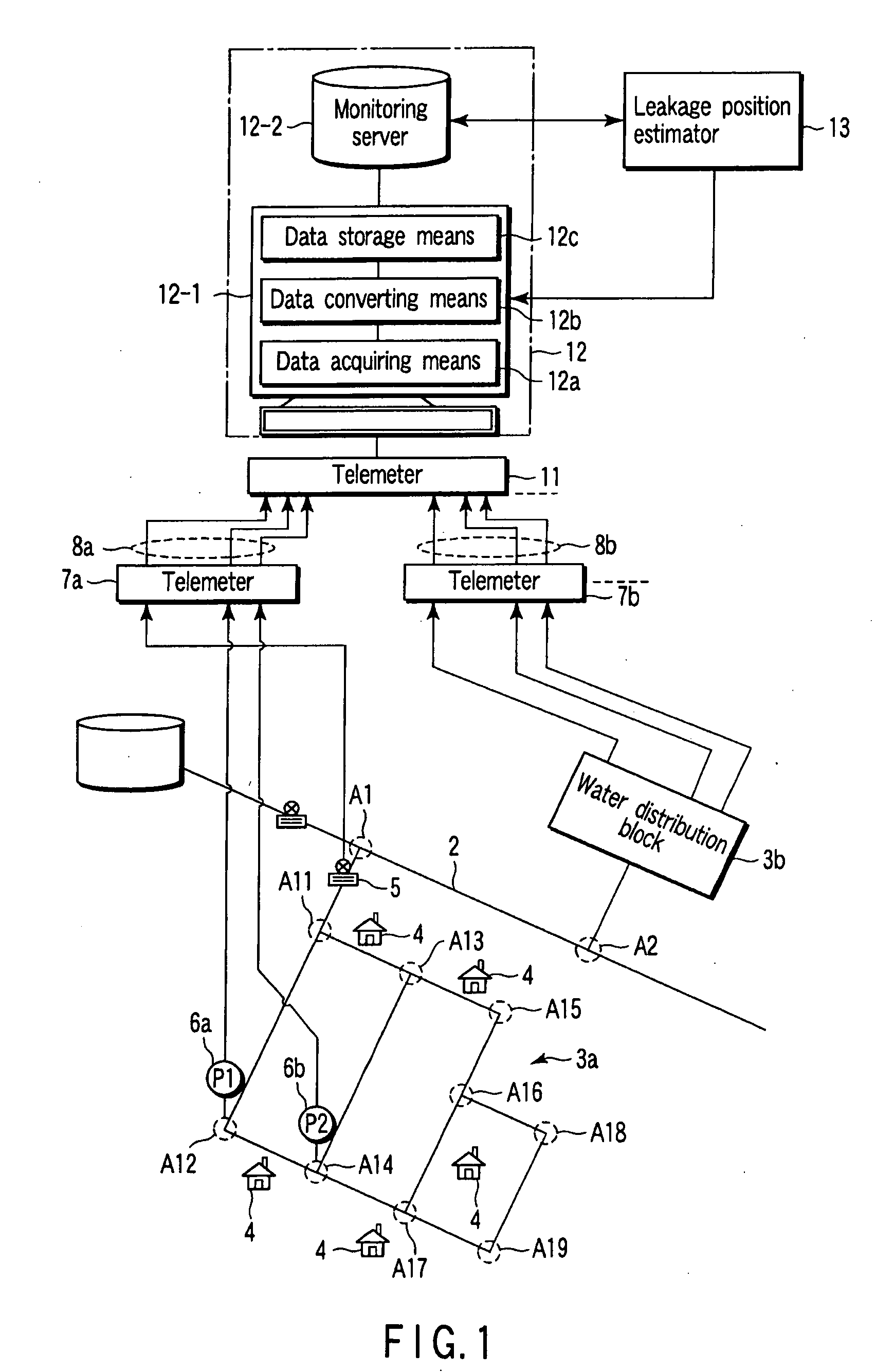
[0052]FIG. 3 is a block diagram showing the configuration of a water leakage monitoring system to explain a first embodiment of the water leakage position estimator 13 according to the present invention.

[0053]The water leakage monitoring system is provided with a water distribution pipeline network map creator 14 in addition to the foregoing monitoring device 12 and water leakage position estimator 13.

[0054]The water distribution pipeline network map creator 14 is provided with a mapping device 14-1 and a pipeline network map database 14-2. The mapping device 14-1 generates a pipeline network connecting a main trunk line, distribution blocks 3a, 3b, . . . and (equipments) such as flow meters 5, and pressure gauges 6 located in the main trunk line and the distribution blocks 3a, 3b, . . . as an image display generated on the basis of a water distribution pipeline network design. The mapping device 14-1 creates a water distribution pipeline network map defining a locating position sho...

second embodiment

[0084]FIG. 7 is a block diagram showing the configuration of a water leakage monitoring system to explain a second embodiment of a water leakage position estimator according to the present invention.

[0085]A water leakage position estimator 13 of the second embodiment has approximately the same configuration as FIG. 3 described in the first embodiment. Thus, the same reference numerals are used to designate the identical or equivalent portions, and the explanation of FIG. 3 is applied. In the following description, different portions will be described in particular.

[0086]According to this embodiment, the water leakage position estimator 13 is newly provided with the following two means in addition to configuration means of the first embodiment. One is bore specifying reference data storage means 26, and another is pipeline bore specifying means 27 for specifying a bore of a pipeline having a flow rate change.

[0087]The bore specifying reference data storage means 26 is stored with ref...

third embodiment

[0099]FIG. 10 is a block diagram showing the configuration of a water leakage monitoring system to explain a third embodiment of a water leakage position estimator according to the present invention.

[0100]Prior to the explanation of this embodiment, the following theoretical physical modulus has been known. The pressure propagation velocity is estimated by the foregoing pressure propagation velocity estimating means 23. In addition, the pressure propagation velocity is obtained from the following physical equation (1) (“Doboku Kogaku Kiso Series 5-2 Hydraulics”, pp. 150-152, Author: Mr. Nobuyuki TAMAI, Publisher: Baifukan, Published date: 1989, 1, 10)

α={(K / ρ) / [1+(K / E)(D / e)]}1 / 2   (3)

[0101]where, α: Pressure propagation velocity, K: Volume elasticity (2.06 [GPa] in water), ρ: Water density (1000 [kg / m3]) D: Pipe bore [mm], e: Pipe wall thickness [mm], E: Young's modulus 158 [GPa] (Case of ductile iron pipe)

[0102]Thus, it can be seen from the foregoing equation (3) that the pressure p...


PUM


Abstract

A water leakage monitoring system including a water leakage position estimator which includes a periodic data acquiring unit for fetching predetermined-period flow rate pressure data stored in a monitoring device, and for fetching a signal related to a flow rate change and pressure changes expecting a water leakage reaction time calculating unit for calculating a pressure reaction time lag between two pressure changes, a pressure propagation velocity estimating unit for estimating a pressure propagation velocity using the pressure reaction time lag and a distance between two pressure gauges located in a water distribution block stored in a pipeline network map data, and a flow rate change position estimating unit for receiving a signal related to the flow rate change, and estimating a flow rate change position using pressure propagation velocity and a flow meter and pressure gauge locating positions of the pipeline network map data.

Description

CROSS-REFERENCE TO RELATED APPLICATIONS[0001]This is a Continuation Application of PCT Application No. PCT / JP2007 / 066737, filed Aug. 29, 2007, which was published under PCT Article 21(2) in Japanese.[0002]This application is based upon and claims the benefit of priority from prior Japanese Patent Application No. 2006-243143, filed Sep. 7, 2006, the entire contents of which are incorporated herein by reference.BACKGROUND OF THE INVENTION[0003]1. Field of the Invention[0004]The present invention relates to a water leakage monitoring system, which estimates leakage positions in water distribution blocks forming a water distribution pipeline network.[0005]2. Description of the Related Art[0006]Water purified by a public water treatment plant is supplied to a large number of customers spread over a large-area district via a water distribution pipeline network. Therefore, the water distribution pipeline network functions as an essential lifeline network to maintain customers' daily life. ...

Claims


Application Information

Patent Timeline
IPC IPC(8): G08B21/00
CPCG01M3/2815
Inventor YUKAWA, ATSUSHIYOKOKAWA, KATSUYAOISHI, NAOTO
Owner TOSHIBA INFRASTRUCTURE SYST & SOLUTIONS CORP
Why Eureka
Try Eureka