Wireless communication device

a wireless communication and wireless communication technology, applied in antennas, modular arrays, antenna details, etc., can solve problems such as efficiency degradation, and achieve the effect of improving antenna efficiency

Inactive Publication Date: 2009-03-12
SHARP KK
View PDF4 Cites 85 Cited by
  • Summary
  • Abstract
  • Description
  • Claims
  • Application Information

AI Technical Summary

Benefits of technology

[0006]An object of the present invention is to provide a wireless communication device including an antenna-integrated module which realizes a high-end antenna having an improved antenna efficiency.
[0010]According to this characteristic, the diameter e of the through hole satisfies λ / 1.706≦e≦λ / 1.3065, where λ is the wavelength of the radiating wave. The dimension of e=λ / 1.706 causes TE11 mode of circular waveguide to be cut off. When e=λ / 1.3065 is satisfied, TM01 which is first higher mode of the circular waveguide is cut off. When e<λ / 1.706 is satisfied, the TE11 mode is cut off and is greatly attenuated (there is no other mode which can be propagated). When e>λ / 1.3065 is satisfied, a part of the TE11 mode is converted into the TM01 mode. This causes a deterioration in efficiency. Therefore, by causing the diameter e to satisfy λ / 1.706≦e≦λ / 1.3065, it is possible to propagate, with low loss, only TE11 mode most suitable for radiation.

Problems solved by technology

This causes a deterioration in efficiency.

Method used


Image

  • Wireless communication device
  • Wireless communication device
  • Wireless communication device

Examples


embodiment 1

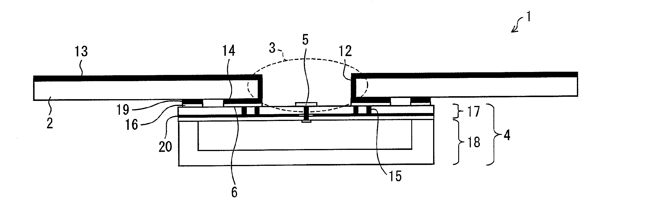
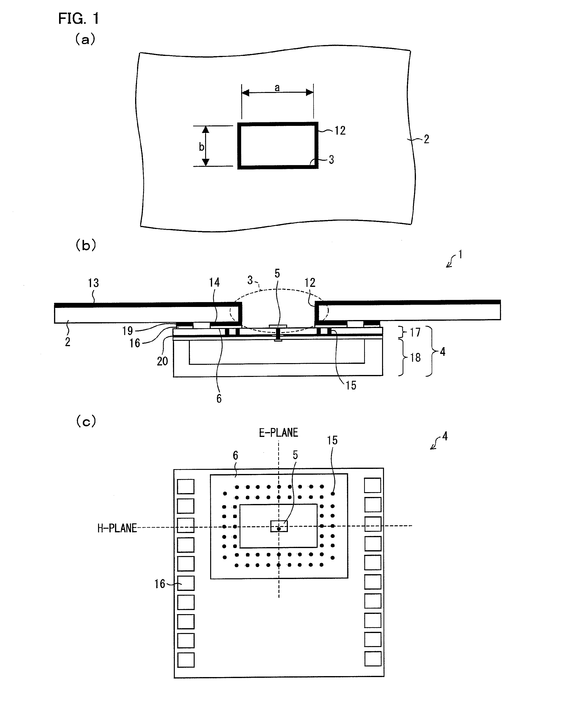
[0022]FIG. 1 is a drawing showing an arrangement of a wireless communication device 1 in accordance with an Embodiment 1, (a) of FIG. 1 is a plan view of a mounting board 2 provided in the wireless communication device 1, (b) of FIG. 1 is a cross-sectional view of the wireless communication device 1, and (c) of FIG. 1 is a plan view of an antenna-integrated module 4 provided in the wireless communication device 1.

[0023](c) of FIG. 1 is a drawing obtained when the antenna-integrated module 4 is seen from a surface on which an antenna is provided. (a) of FIG. 1 shows lengths a and b of a through hole 3 provided in the mounting board 2.

[0024]The wireless communication device 1 includes the mounting board 2. The mounting board 2 has the through hole 3 having a rectangular cross-sectional shape. The antenna-integrated module 4, covering the through hole 3, which is mounted onto the mounting board 2 is provided in the wireless communication device 1. The antenna-integrated module 4 has a ...

embodiment 2

[0045]FIG. 5 is a drawing showing an arrangement of a wireless communication device 1a in accordance with an Embodiment 2. (a) of FIG. 5 is a plan view of a mounting board 2a provided in the wireless communication device 1a. (b) of FIG. 5 is a cross-sectional view of the wireless communication device 1a. (c) of FIG. 5 is a plan view of an antenna-integrated module 4a provided in the wireless communication device 1a.

[0046]Constituent members which are identical with or similar to those in Embodiment 1 are given identical or similar reference numerals and are not explained repeatedly. The difference from the Embodiment 1 resides in that an annular grounding sheet 6a and a through hole 3a have circular openings.

[0047]The wireless communication device 1a includes the mounting board 2a. The through hole 3a whose cross-sectional shape is circular is formed in the mounting board 2a. In the wireless communication device 1a, the antenna-integrated module 4a is mounted on the mounting board ...

embodiment 3

[0056]FIG. 8 is a drawing showing an arrangement in which a mortar structure 26 and a dielectric lens 25 are provided in the wireless communication device 1 described in the Embodiment 1, (a) of FIG. 8 is a plan view of the arrangement, and (b) of FIG. 8 is an elevation cross-sectional view of the arrangement.

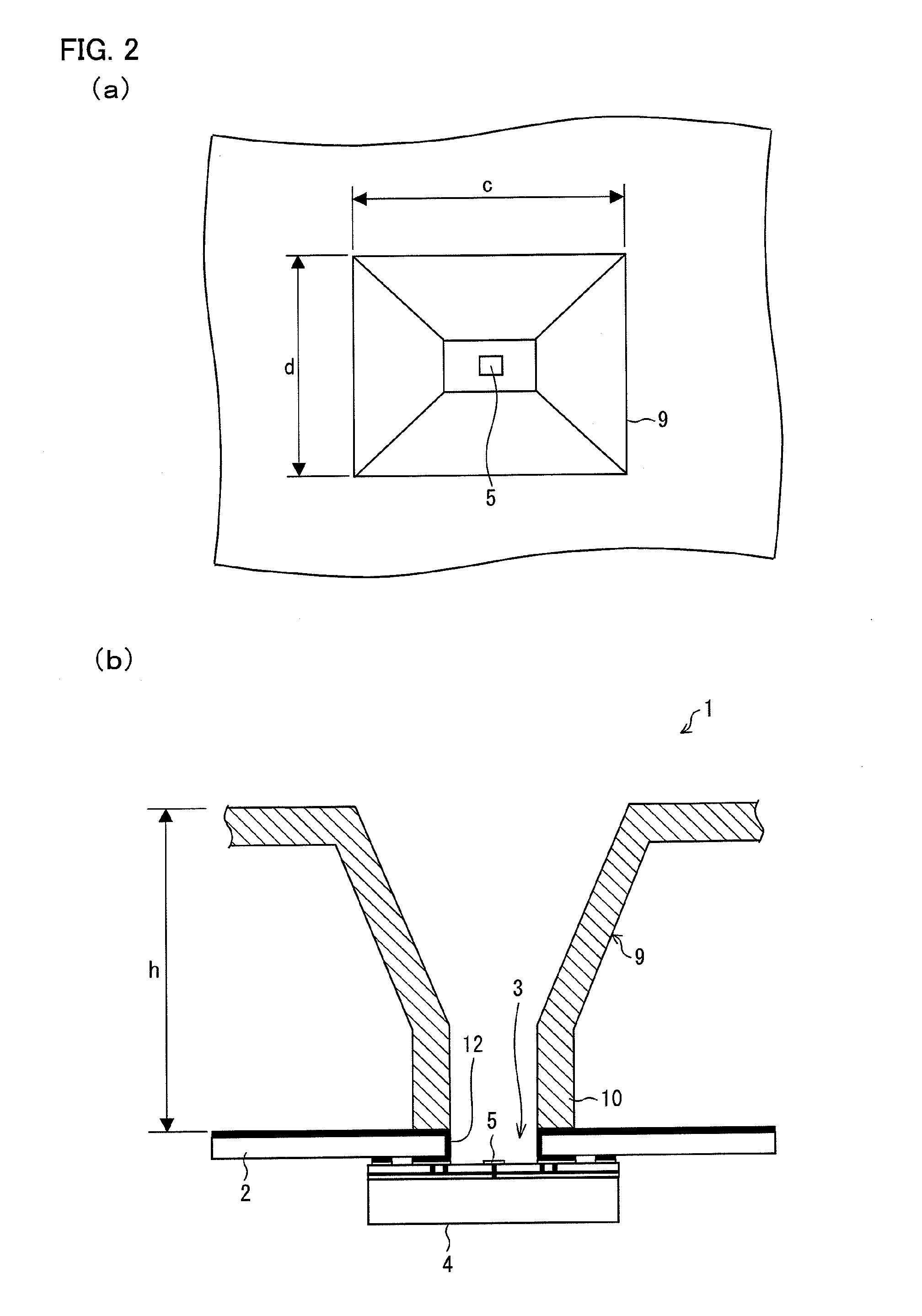
[0057]Such an arrangement is different from the horn antenna 9 shown in FIG. 2 in that (i) the mortar structure 26 having a lower circular opening 27 and an upper circular opening 28 is provided above a through hole 3b, and (ii) the dielectric lens 25 is provided so as to cover the upper circular opening 28. The mortar structure 26 is set to have a depth H so that the dielectric lens 25 has a focal point positioned on the center of the lower circular opening 27.

[0058]Further, the through hole 3b shown in (a) of FIG. 8 is an exemplary through hole formed by a drill. Each of shorter sides of the through hole 3b has a semicircular shape.

[0059]The lower circular opening 27 of the m...


PUM


Abstract

A wireless communication device including an antenna-integrated module which realizes a high-end antenna having an improved antenna efficiency includes a mounting board having a through hole whose cross-sectional shape is rectangular; and an antenna-integrated module mounted on the mounting board so as to cover over the through hole, a patch antenna, which radiates radiation wave, being provided on a surface of the antenna-integrated module, which surface is exposed in the through hole, an annular grounding sheet being provided between the antenna-integrated module and the mounting board so as to surround the patch antenna, and the through hole having a longer side whose length satisfies λ / 2≦a≦λ, where λ is a wavelength of the radiation wave.

Description

[0001]This Nonprovisional application claims priority under U.S.C. §119(a) on Patent Application No. 233431 / 2007 filed in Japan on Sep. 7, 2007 and Patent Application No. 172496 / 2008 filed in Japan on Jul. 1, 2008, the entire contents of which are hereby incorporated by reference.FIELD OF THE INVENTION[0002]The present invention relates to a microwave and millimeter-wave wireless communication device having an antenna function.BACKGROUND OF THE INVENTION[0003]In recent years, wireless transmission of a high-definition video image signal has attracted attention. This necessitates transmitting of large capacity information, and therefore there have been attempts to develop a wireless video image transmission device using a millimeter-wave capable of securing a wide band. In a millimeter-wave band, when an antenna and a high frequency circuit are separately prepared and are then connected with each other via a connecting member such as a connecter, a large power loss occurs at their co...

Claims


Application Information

Patent Timeline
Patent Type & Authority Applications(United States)
IPC IPC(8): H01Q1/24H01Q19/06
CPCH01Q13/02H01Q21/0025H01Q19/062
Inventor YAMADA, ATSUSHISATOH, KEISUKETANAKA, HIROKI
Owner SHARP KK
Why Eureka
Try Eureka