Steam Generator

a generator and steam technology, applied in the direction of steam generation using hot heat carriers, steam separation arrangements, lighting and heating apparatuses, etc., can solve the problems of considerable restrictions in operating flexibility, inability to achieve phase separation, and inability to operate in low-load operation, etc., to achieve short reaction times, high degree of operating flexibility, and low cost

Active Publication Date: 2009-03-19
SIEMENS ENERGY GLOBAL GMBH & CO KG
View PDF15 Cites 14 Cited by
  • Summary
  • Abstract
  • Description
  • Claims
  • Application Information

AI Technical Summary

Benefits of technology

[0021]The advantages achieved by the invention are in particular that as a result of the water separation being integrated in the tube system of the steam generator, the water separation can be effected without prior collection of the flow medium flowing out of the evaporator tubes and without subsequent distribution of the flow medium passed on to the superheater tubes. Consequently, it is possible to avoid the need for complex collection and distribution systems. Furthermore, the elimination of complex distribution systems means that the transfer of flow medium to the superheater tubes is not restricted to steam alone; rather, it is now also possible for a water-steam mixture to be passed on to the superheater tubes. In particular as a result, the evaporation end point can be shifted beyond the location of separation between evaporator tubes and superheater tubes, if necessary into the superheater tubes themselves. This allows a particularly high degree of operating flexibility to be achieved even in start-up or low-load operation of the once-through stream generator.
[0022]Furthermore, the water separation elements may in particular also be designed as T-pieces based on the piping of the once-through steam generator which is already present in any case. These T-pieces can be of relatively thin-walled design, in which case diameter and wall thickness can be kept approximately equal to those of the wall tubes. Therefore, the thin-walled design of the water separation elements means that the start-up times of the boiler as a whole or also the load change speeds are not limited any further, so that relatively short reaction times in the event of load changes can be achieved even in installations for high stream states. Moreover, T-pieces of this type can be produced at particularly low cost. In particular, even temporary over-feeding of the separation elements when starting up or in low-load operation is permissible, so that some of the evaporator water which is to be discharged can be collected in the superheater tubes connected downstream of the evaporator tubes. This allows the water collection systems, such as for example the separation cylinders or the outlet valves, to be designed for correspondingly smaller outlet quantities, making them less expensive. Furthermore, the shift in the evaporation end point into the superheater tubes makes it possible to limit any water injection which may be required, with the associated losses.

Problems solved by technology

A once-through steam generator, unlike a natural or forced circulation steam generator, is not subject to any pressure restrictions, and consequently it can be designed for live steam pressures well above the critical pressure of water (PCri≈221 bar), where it is not possible to distinguish between the water and steam phases and therefore phase separation is also not possible.
In particular at low loads of, for example, less than 40% of the design load, the once-through mass flow through the steam generator tubes corresponding to the associated steam power is usually no longer sufficient to cool these tubes, and consequently an additional throughput of flow medium is superimposed on this once-through passage of flow medium through the evaporator.
Consequently, the operating flexibility of this type of design of once-through steam generator is considerably restricted in low-load operation.
The required choice of materials likewise leads to considerable restrictions in operating flexibility.
The resulting relatively large dimension of separation cylinder and outlet valves leads to considerable production and assembly costs.

Method used


Image

  • Steam Generator
  • Steam Generator
  • Steam Generator

Examples


Embodiment Construction

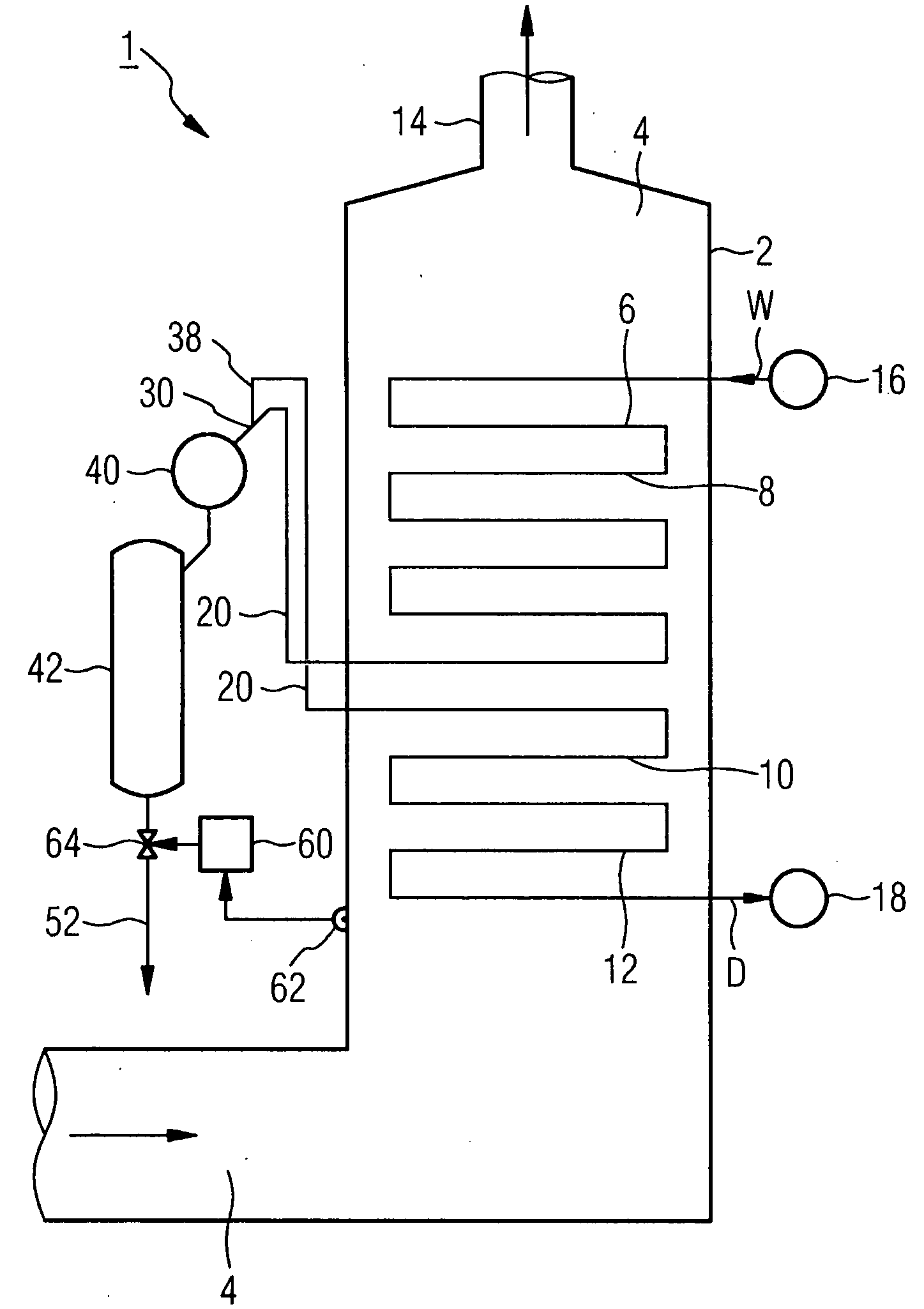
[0028]The steam generator 1 shown in FIG. 1 is designed as a once-through steam generator and, as part of a combined-cycle gas and steam turbine installation, is connected, in the form of a heat recovery steam generator, downstream of a gas turbine (not shown in more detail) on the exhaust gas side. The steam generator 1 has a boundary wall 2 which forms a heating gas passage 4 for the exhaust gas from the gas turbine. An evaporator once-through heating surface 8, formed from a number of evaporator tubes 6, and a superheater heating surface 12, which is connected downstream of the evaporator once-through heating surface 8 for the flow of a flow medium W, D and is formed from a number of superheater tubes 10, are arranged in the heating gas passage 4. In terms of the routing of the exhaust-gas stream from the gas turbine, the superheater heating surface 12 is arranged upstream of the evaporator once-through heating surface 8, with the result that the exhaust gas from the gas turbine ...


PUM


Abstract

The invention relates to a steam generator wherein a continuous heating panel of a generator, which is formed from a number of evaporator tubes, and an overheating panel, which is formed from a number of over-heating tubes which are arranged downstream from the evaporator tubes and on the flow side, are arranged in a heating gas channel. According to the invention, a water separating element is integrated into a number of over-flow tubes which are connected on the flow side of one of several evaporator tubes to one or several overheating tubes.

Description

CROSS REFERENCE TO RELATED APPLICATIONS[0001]This application is the US National Stage of International Application No. PCT / EP2006 / 061225, filed Mar. 31, 2006 and claims the benefit thereof. The International Application claims the benefits of European application No. 05007413.7 filed Apr. 5, 2005, both of the applications are incorporated by reference herein in their entirety.FIELD OF INVENTION[0002]The invention relates to a steam generator, in which an evaporator once-through heating surface, formed from a number of evaporator tubes, and a superheater heating surface, formed from a number of superheater tubes connected downstream of the evaporator tubes on the flow medium side, are arranged in a heating gas passage.BACKGROUND OF THE INVENTION[0003]In a once-through steam generator, the heating of a number of evaporator tubes leads to complete evaporation of the flow medium in the evaporator tubes in one pass. The flow medium—usually water—, after it has been evaporated, is fed to...

Claims


Application Information

Patent Timeline
Patent Type & Authority Applications(United States)
IPC IPC(8): F22B1/18F22B9/00F22B29/06
CPCF22B29/06F22B1/1815
Inventor FRANKE, JOACHIMKRAL, RUDOLF
Owner SIEMENS ENERGY GLOBAL GMBH & CO KG
Why Eureka
Try Eureka