
Strutless type umbrella
a technology of umbrellas and struts, applied in umbrellas, walking sticks, clothing, etc., can solve the problems of not being able to meet the requirements easily, and achieve the effect of reducing thickness
- Summary
- Abstract
- Description
- Claims
- Application Information
AI Technical Summary
Benefits of technology
Problems solved by technology
Method used
Image

Examples
Embodiment Construction
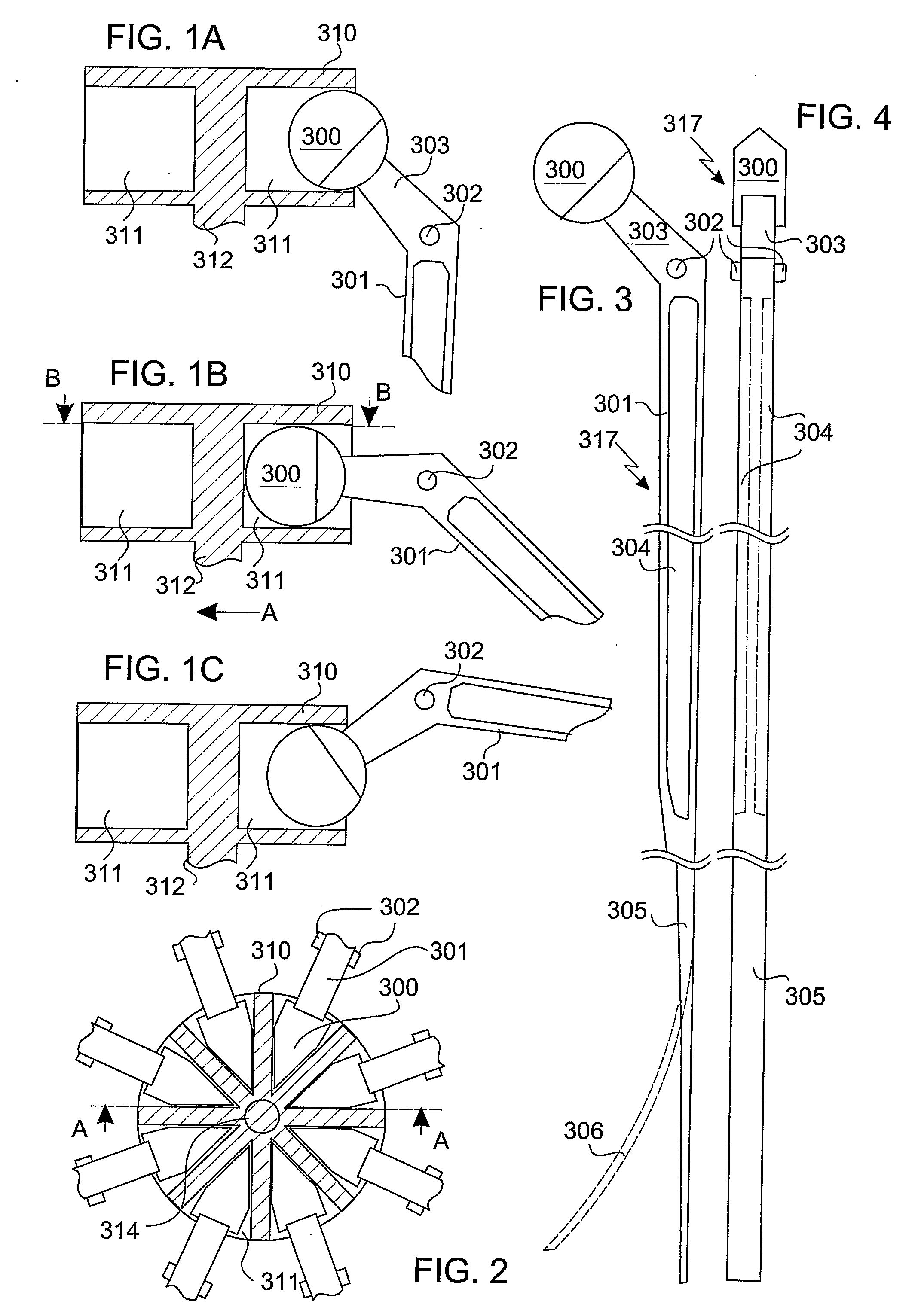
[0036]Referring to FIGS. 1A-1C and 2, there is illustrated an example of a canopy conducting mechanism of the present invention, which in the present example is based on a pin-and-slide joint. The latter is of the type defining an elongated contact region between a pin (i.e., a cylindrically-like element with circular or other rounded base surfaces) and a slide plane, the contact region thus being a line along the cylinder-like generator. FIGS. 1A-1C show, in partial vertical cross section view (taken at A-A of FIG. 2), three operational states, respectively, of the mechanism, and FIG. 2 shows a partial lateral cross section view (taken at B-B of FIG. 1B) of the canopy conducting mechanism in its state of FIG. 1B.
[0037]In the illustrated embodiment, a pin 300 of the pin-and-slide joint is actually the end portion of a rib lever 303 of an umbrella rib body 301. Pin 300 is also referred to in the context of the present invention as “the free end of the rib lever”. In this example, pin...
PUM
 Abstract
Description
Claims
Application Information