Arrangement for Reducing a Rotational Speed of a Rotating Member

a technology of rotating parts and rotational speed, which is applied in the direction of friction clutches, brake types, slack adjusters, etc., can solve the problems of deteriorating the spring effect of the washer, and achieve the effect of sufficient spring effect and long li

Inactive Publication Date: 2009-03-19
VOLVO CONSTR EQUIP
View PDF10 Cites 6 Cited by
  • Summary
  • Abstract
  • Description
  • Claims
  • Application Information

AI Technical Summary

Benefits of technology

[0007]Due to the fact that the spring means will not, at any time, be compressed to the totally compressed state, it will not be subjected to as large loads as prior art devices and thus have a longer life. Further, the automatic return function and constant clearance is achieved in one single apparatus, which creates conditions for a cost-efficient production and installation. More specifically, the adjustment device may be pre-mounted.
[0008]According to a preferred embodiment, the friction means is at least partly arranged in an opening in the pressure part and that an outer surface of the friction means and a peripheral wall of the opening have a complementary design for forming the friction joint. This design creates further conditions for a cost-efficient production and installation. Only one hole is required in one of the pressure members. According to a f

Problems solved by technology

One disadvantage with this arrangement is that the spring effect of the washer

Method used


Image

  • Arrangement for Reducing a Rotational Speed of a Rotating Member
  • Arrangement for Reducing a Rotational Speed of a Rotating Member
  • Arrangement for Reducing a Rotational Speed of a Rotating Member

Examples


Embodiment Construction

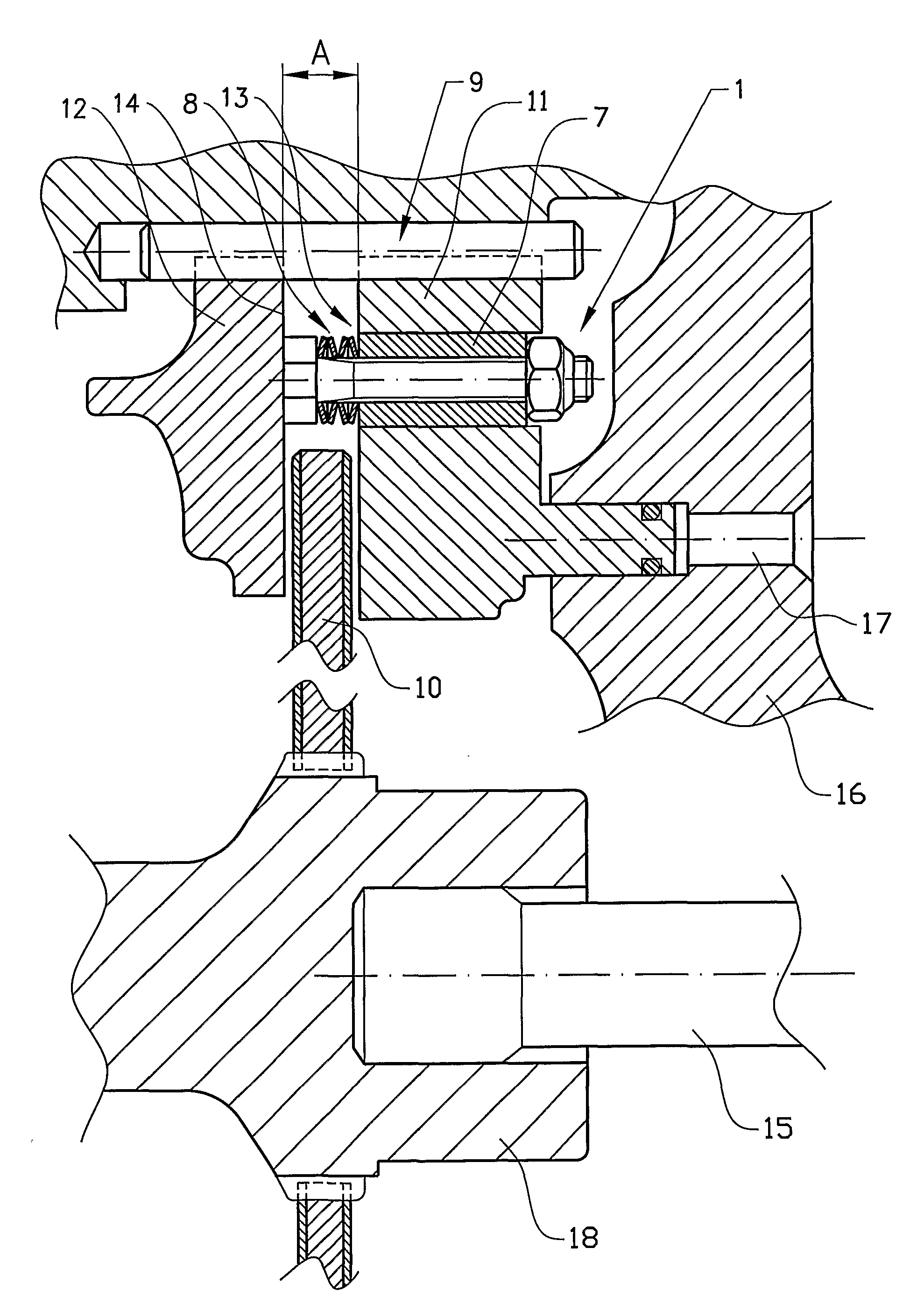
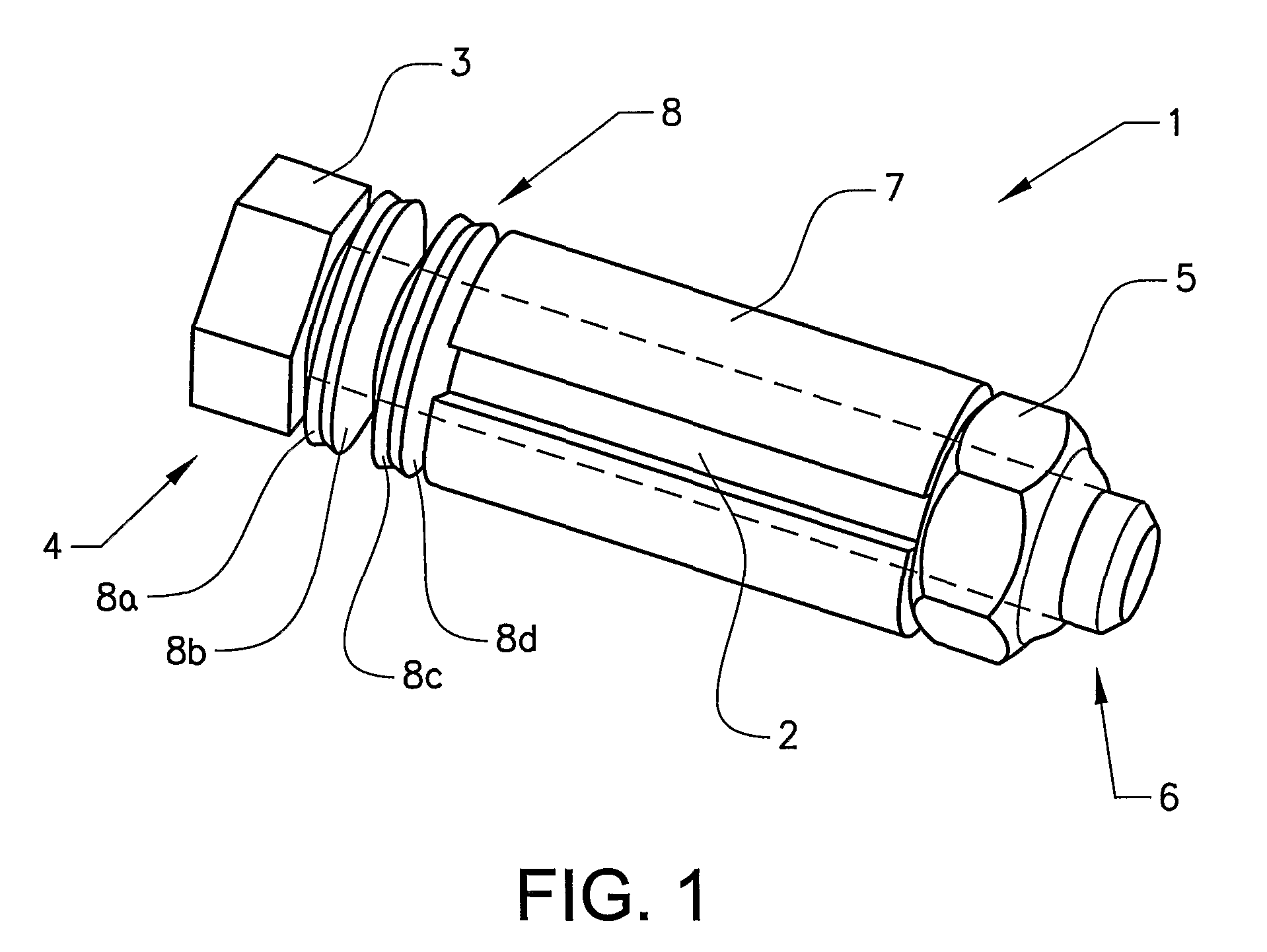
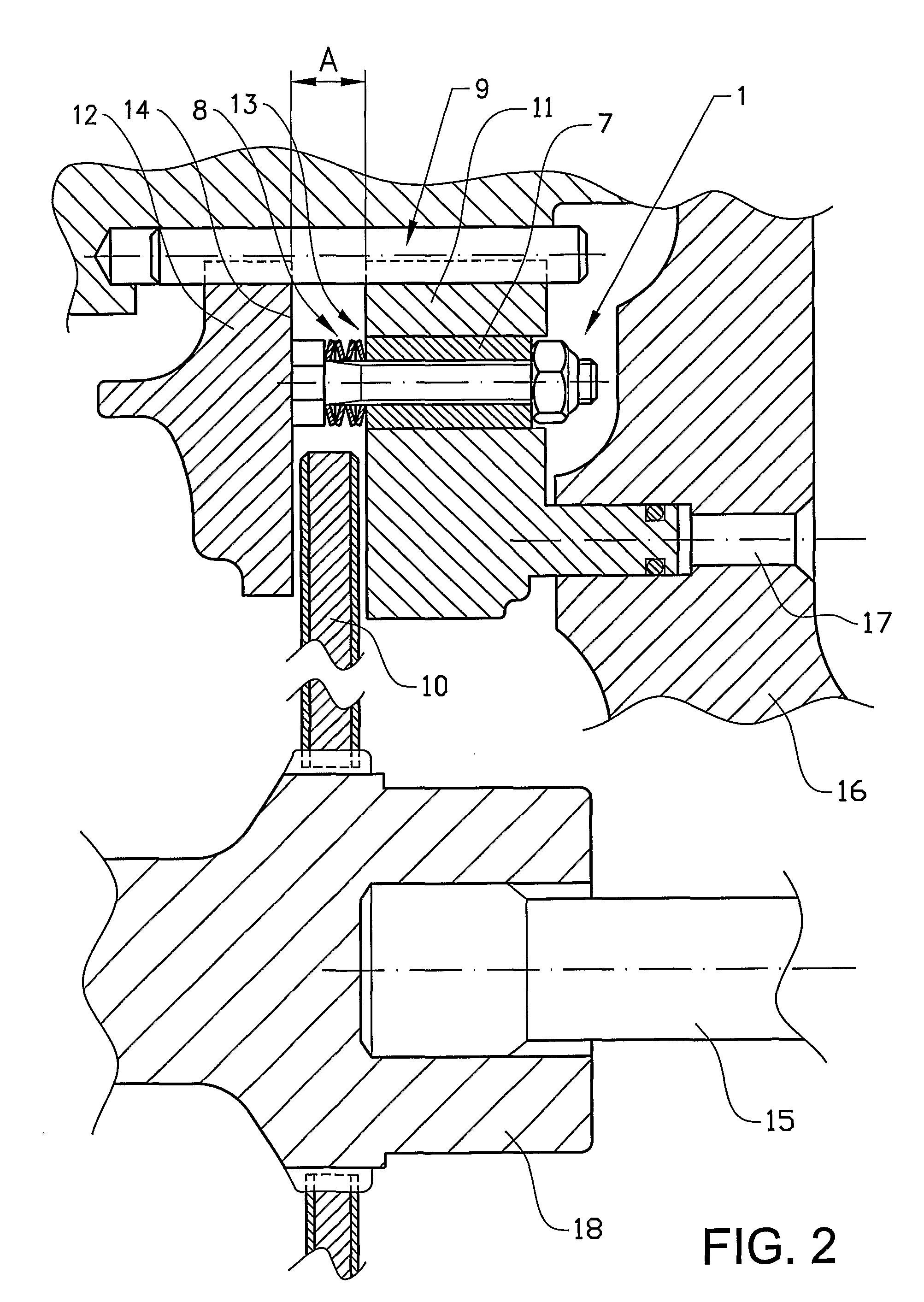
[0018]FIG. 1 illustrates a first embodiment of an adjustment device 1 suitable for a hydraulic brake in a perspective view. The adjustment device 1 comprises an elongated support portion 2, or pin, in the form of a bolt shank. A first end portion 3, in the form of a bolt head, is fixed at a first end 4 of the support portion 2, forming a one-piece unit. A second end portion 5, in the form of a hex nut, is fixed at a second end 6 of the support portion 2. The support portion 2, the first end portion 3 and the second end portion 5 will below be referred to as bolt shank, bolt head and nut for ease of presentation.

[0019]A friction means 7 in the form of a split tubular member, or sleeve, is arranged co-axially around the bolt shank 2. The friction means 7. is freely movable relative to the bolt shank 2 in its longitudinal direction. A spring means 8 is arranged around the bolt shank 2 beside the tubular friction means 7. Said spring means 8 comprises a plurality of hollow, dished disct...


PUM


Abstract

An arrangement for reducing a rotational speed of a rotating member includes a first and second pressure member arranged at a distance from each other and an opposite sides of the rotating member for movement relative to each other between a retracted position and a forward position engaging the rotating member. The arrangement includes an adjustment device including a friction structure forming a friction joint with one of the pressure members for maintaining a position relative to one another provided a maximum friction force is not exceeded. The arrangement further includes a spring acting on the friction structure for separating the pressure members after having been compressed. The spring has a gradually increasing spring force between a non-compressed state and a totally compressed state. An intermediate spring force value of the spring, which corresponds to compression of the spring to an extent less than the totally compressed state, equals a maximum friction force of the friction joint so that the friction structure is forced to move relative to the pressure member, with which it forms the friction joint, when the maximum friction force is exceeded.

Description

BACKGROUND AND SUMMARY[0001]The present invention relates to an arrangement for reducing a rotational speed of a rotating member. The arrangement comprises a first and second pressure member arranged at a distance from each other and on opposite sides of the rotating member. The first and second member are movable relative to each other between a retracted position and a forward position engaging the rotating member. The invention is particularly suitable for application in a hydraulic disc brake in which the pressure members are pressed against opposite faces of a brake disc to provide frictional resistance to its rotation.[0002]The arrangement comprises an adjustment device comprising a friction means forming a friction joint with one of said pressure members for maintaining a position relative to one another provided a maximum friction force is not exceeded. The arrangement further comprises a spring means acting on the friction means for separating the pressure members after hav...

Claims


Application Information

Patent Timeline
IPC IPC(8): F16D65/54
CPCF16D65/54
Inventor STRANDBERG, JONNYANDERSSON, THOMAS
Owner VOLVO CONSTR EQUIP
Why Eureka
Try Eureka