Apparatus and method for arranging magnetic solder balls

a technology of magnetic soldering and apparatus, which is applied in the direction of soldering apparatus, non-printed mask,auxillary welding devices, etc., can solve the problems of high processing cost, coagulation of soldering balls, and inability to accurately dispose of soldering balls, so as to prevent the occurrence and prevent the occurren

Inactive Publication Date: 2009-03-19
SHINKO ELECTRIC IND CO LTD
View PDF0 Cites 19 Cited by
  • Summary
  • Abstract
  • Description
  • Claims
  • Application Information

AI Technical Summary

Benefits of technology

[0032]According to the first invention of the invention, the magnet incorporated in the stage with the substrate placed and fixed thereon is used as a dropping means, and the magnetic solder balls are moved on the mask by moving the magnet below the stage while a magnetic force is being applied to the magnetic solder balls on the mask located above the stage, thereby dropping the magnetic solder balls into the openings of the mask so as to mount the magnetic solder balls on the bonding pads located below the openings. Therefore, the magnetic solder balls can be dropped in a mechanically non-contacting state. Hence, it is possible to prevent the occurrence of the damage to, deformation of, and commingling of foreign matter with, the solder balls, which unavoidably occurred in the dropping based on the mechanical contact using a conventional spatula or brush as...

Problems solved by technology

When the solder balls thus become infinitesimally small, there arise problems that the solder balls coagulate due to the action of static electric charge, and that the solder balls cannot be disposed at accurate positions owing to the effect of air flow.
In addition, suction ports of the suction jig are also miniaturized, so that the processing cost becomes high, which is not suitable for practical use.
However, if the mechanical forcible movement by means of the spatula or the...

Method used


Image

  • Apparatus and method for arranging magnetic solder balls
  • Apparatus and method for arranging magnetic solder balls
  • Apparatus and method for arranging magnetic solder balls

Examples


first embodiment

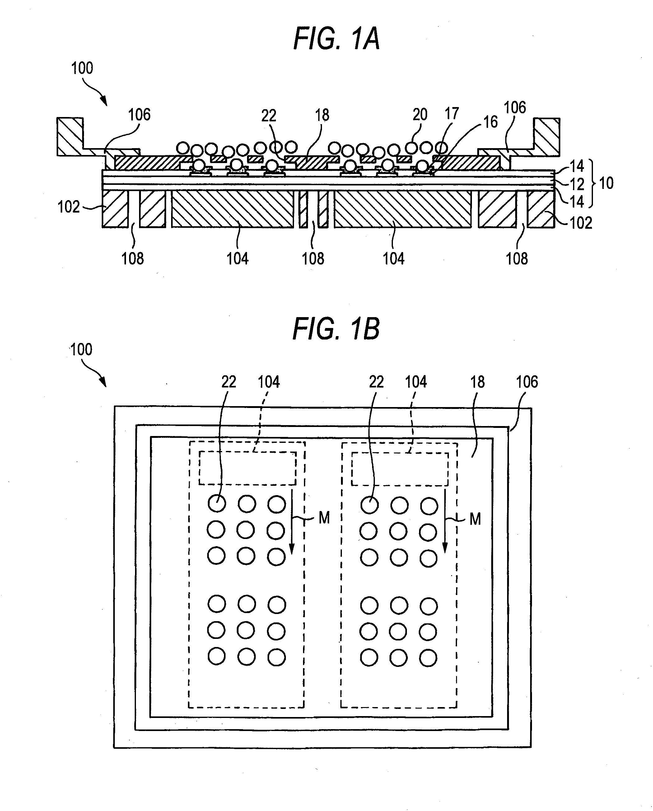
[0039]Referring to FIGS. 1A and 1B, a description will be given of an apparatus for arranging magnetic solder balls in accordance with the invention. FIG. 1A is a cross-sectional view, and FIG. 1B is a plan view.

[0040]An arranging apparatus 100 is comprised of a stage 102 for placing and fixing a substrate 10 thereon; magnets 104 which are incorporated in the stage 102 and are movable in parallel with the lower surface of the placed and fixed substrate 10 so as to cause a magnetic force to act in the upward direction of the stage 102; and a mask frame 106 capable of being positioned above the stage 102. The arranging apparatus 100 is an apparatus for arranging magnetic solder balls 20 one each on each of a plurality of bonding pads 16 on the substrate 10 through a mask 18.

[0041]The substrate 10 is a multilayered circuit board in which a wiring layer and an insulating layer are laminated on both surfaces of a resin-made core substrate having through holes and the like by means of the...

second embodiment

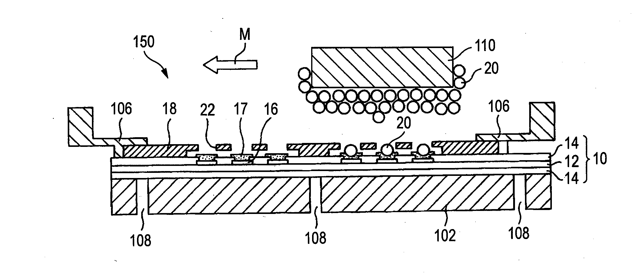
[0051]Referring to FIG. 3, a description will be given of the apparatus for arranging magnetic solder balls in accordance with the second invention.

[0052]An arranging apparatus 150 is comprised of a stage 102 for placing and fixing the substrate 10 thereon; the mask frame 106 capable of being positioned above the stage 102; and a magnetic head 110 serving as a magnetic generator which is movable above the mask frame 106 and causes a magnetic force to act on the stage 102. The arranging apparatus 150 is an apparatus for arranging the magnetic solder balls 20 one each on each of the plurality of bonding pads 16 on the substrate 10 through the mask 18.

[0053]The substrate 10 is a multilayered circuit board in which a wiring layer and an insulating layer are laminated on both surfaces of a resin-made core substrate having through holes and the like by means of the build-up process or the like. The solder resist layer 14 is formed on each of both upper and lower surfaces of the multilayer...


PUM

PropertyMeasurementUnit
Magnetic forceaaaaaaaaaa

Abstract

An apparatus for arranging magnetic solder balls includes: a stage for placing and fixing the substrate thereon; a magnet which is incorporated in the stage and is movable in parallel with a lower surface of the placed and fixed substrate so as to cause a magnetic force to act in an upward direction of the stage; and a mask frame capable of being positioned above the stage. An arranging method using this arranging apparatus is also provided. An apparatus for arranging magnetic solder balls includes: a stage for placing and fixing the substrate thereon; a mask frame capable of being positioned above the stage; and a magnetic generator which is movable above the mask frame and causes a magnetic force to act on the stage. An arranging method using this arranging apparatus is also provided.

Description

BACKGROUND OF THE INVENTION[0001]The present invention relates to an apparatus and a method for arranging magnetic solder balls one each on each of a plurality of bonding pads on a substrate through a mask.[0002]Conventionally, solder paste is screen printed to form solder bumps on bonding pads for flip chip bonding of a substrate such as a wafer or a circuit substrate. However, in conjunction with the trend toward the higher density of semiconductor devices, the bump pitch is required to be infinitesimally small such as on the order of 200 μm or even 150 μm. If solder paste is screen printed at such an infinitesimally small pitch, attachment of the solder paste on a bridge between bumps and on a screen mask occurs. For this reason, the formation of the solder bumps at the infinitesimally small pitch cannot be effected by screen printing.[0003]Accordingly, as a method of forming bumps at an infinitesimally small pitch, it is conceivable to arrange the solder balls on the bonding pad...

Claims


Application Information

Patent Timeline
IPC IPC(8): B23K1/20B23K37/00
CPCB23K3/0623H01L2224/11334H01L24/742H01L2224/11003H01L2224/13147H01L2224/1319H01L2924/0102H01L2924/01029H01L2924/01033H01L2924/3025H05K3/3478H05K2201/083H05K2201/10234H05K2203/041H05K2203/0557H05K2203/104H01L2224/1358H01L2224/13561H01L2224/11005H01L21/4853H01L24/13H01L2224/13582H01L2224/136H01L2224/13655H01L2224/81192H01L2924/01006B23K2201/36H01L2924/014B23K2101/36H01L2224/05567H01L2224/05573H01L2924/00014H01L2224/05599
Inventor SAKAGUCHI, HIDEAKIIIDA, KIYOAKI
Owner SHINKO ELECTRIC IND CO LTD
Why Eureka
Try Eureka