
Self-Tooling Composite Structure

a composite structure and self-tooling technology, applied in the field of manufacturing composite structures, can solve the problems of complex manufacturing tools, unstable structure, and high labor content and other costs, and achieve the effect of avoiding buckling instability, reducing labor intensity and other costs, and reducing labor intensity

Active Publication Date: 2009-03-19
KAREM ABE
View PDF6 Cites 18 Cited by
  • Summary
  • Abstract
  • Description
  • Claims
  • Application Information

AI Technical Summary

Benefits of technology

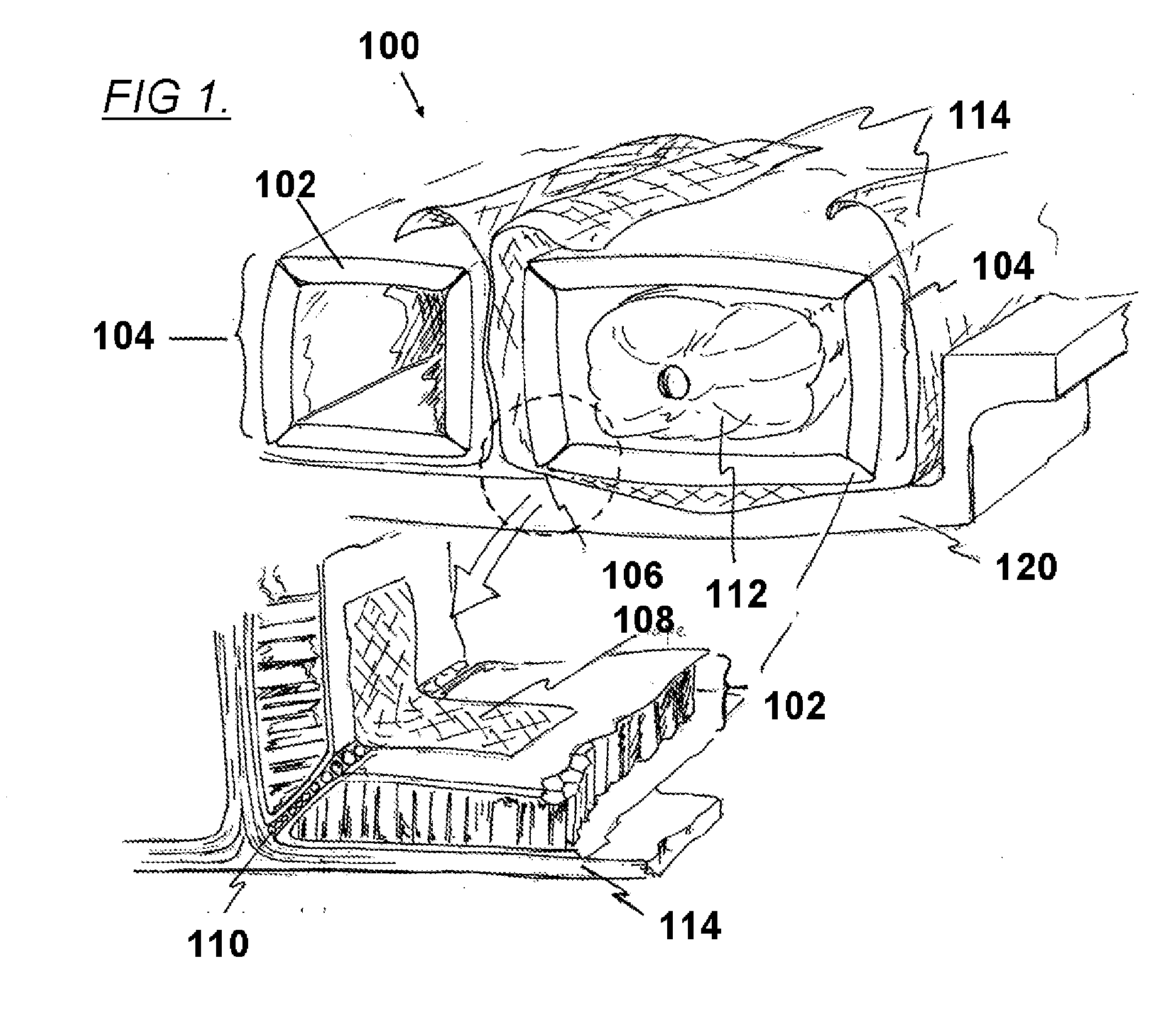
[0009]Contemplated structures include those that are long and slender, especially those with one or more internal cells, in which the cavity bounded by the internal cell has an aspect ratio of at least 5, 10, 15, or even 20. Rotor blades are especially preferred structures; they are usually long and relatively thin, and often have demanding structural requirements well suited to multi-cell composite construction.
[0010]In preferred embodiments, the structure comp

Problems solved by technology

Manufacturing composite structures often requires complex manufacturing tools, with relatively high labor content and other costs.
Additionally, when such structures are designed to the minimum required thickness to provide the specified strength and stiffness, the reduced thickness makes the structure prone to buckling instability.
Design against buckling requires either increased thickness (entailing higher weight and cost) or additional support through adoption of sandwich construction using a lightweight core material.
For most high aspect ratio structures, including helicopter rotor blades, this sandwich construction is impossible or impractical to achieve in the current manufacturing process, as the curing of an enclosed box form at high aspect ratio requires complex tooling or creates inaccessible voids.

Method used


Image

  • Self-Tooling Composite Structure
  • Self-Tooling Composite Structure
  • Self-Tooling Composite Structure

Examples


Embodiment Construction

[0019]The present invention provides apparatus, systems, and methods in which a partially cured composite layer is used as scaffolding for a second layer that is not self-supporting, and the layers are simulcured.

[0020]As used herein, “composite” means engineered materials made from two or more constituent materials. Of special relevance are carbon composites, in which carbon fiber is embedded in a matrix or resin. Alternate composites are also contemplated including those containing fiberglass, ceramics, and other elements. A layer of composite material could include a plurality of fibers positioned at an orientation with respect to the long axis of an object. A matrix or resin material could surround said fibers. In certain applications, the plurality of fibers can advantageously be arranged with an orientation at least 45° from a line normal to the long axis of the object.

[0021]As used herein, a “laminated object” refers to an object made with laminates. These laminates typically...


PUM

PropertyMeasurementUnit
Temperatureaaaaaaaaaa
Thicknessaaaaaaaaaa
Thicknessaaaaaaaaaa

Abstract

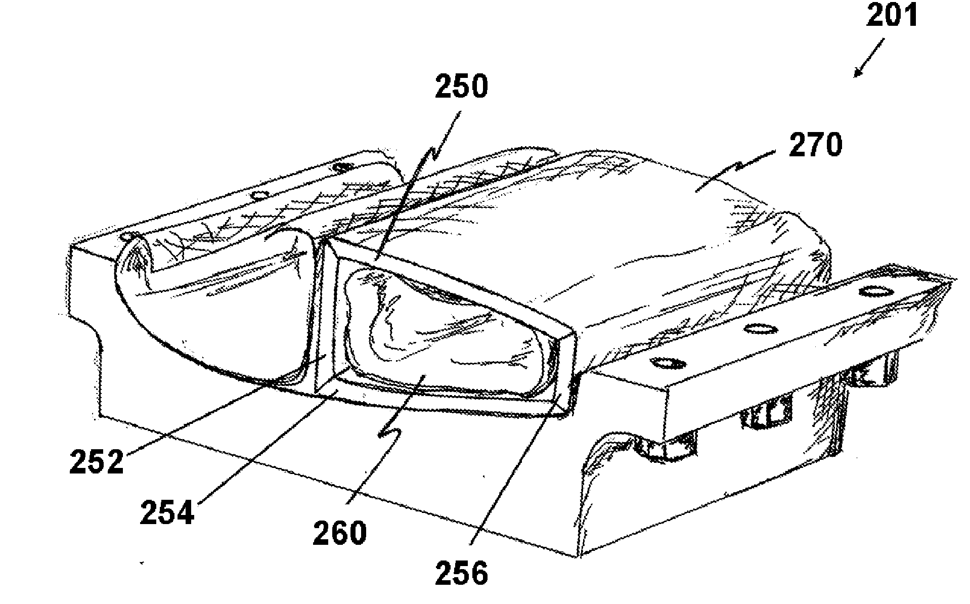
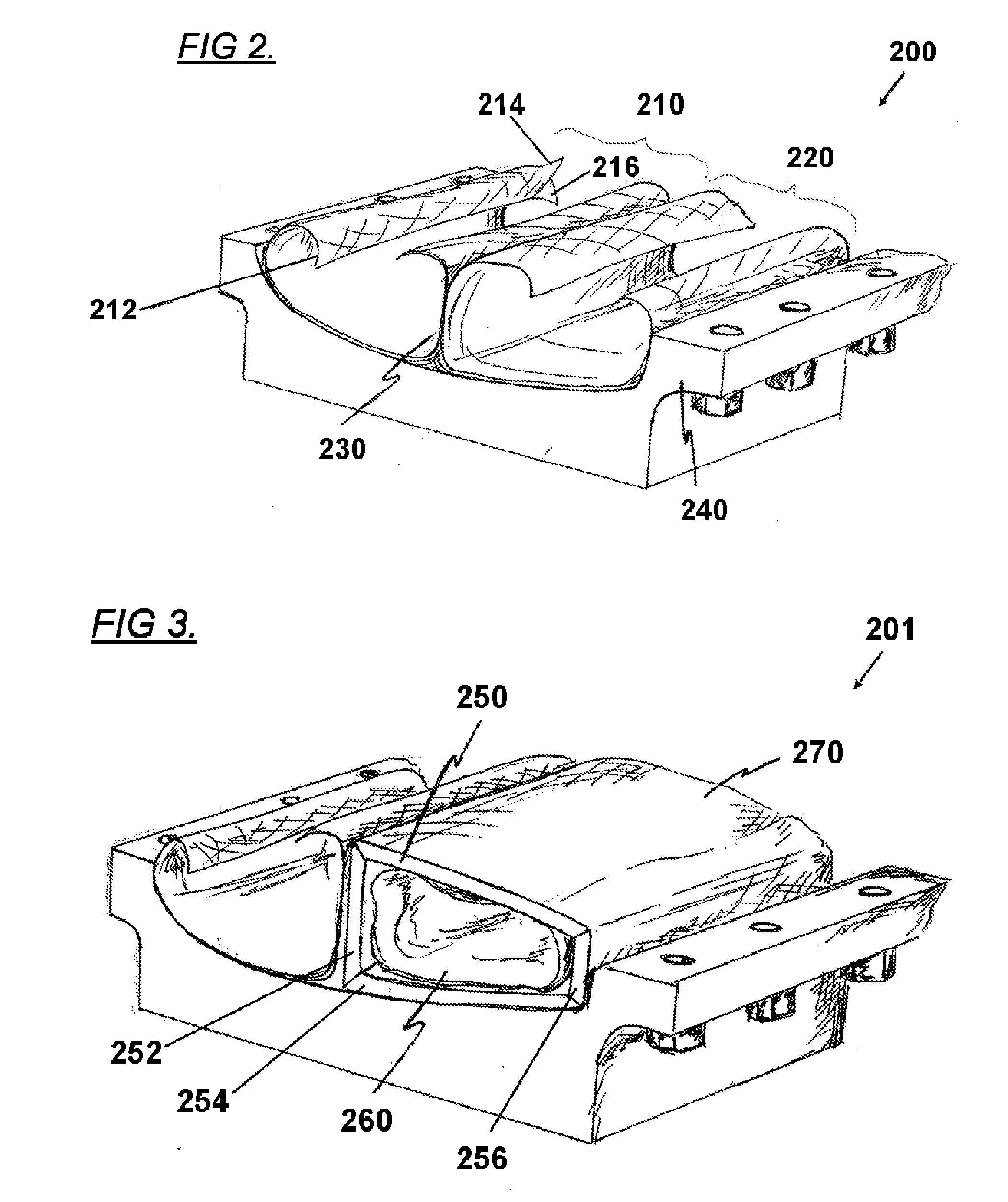
Composite structures with internal cavities are constructed with relatively stiff walls that can support additional composite laminate layers, creating a self-tooling structure. The structure is subsequently simulcured, preferably in combination with elevated temperatures or pressures. Preferred structures are long and slender, and are constructed with one or more internal cells. Rotor blades are especially suited to the preferred construction methods. The walls can be advantageously constructed using composite sandwich panels, having an exterior laminate layer. In preferred embodiments, additional composite layers can be added before or after the simulcuring process.

Description

[0001]This application claims priority to U.S. Provisional Application Ser. No. 60 / 968,489 filed Aug. 28, 2007 which is incorporated by reference herein in its entirety.FIELD OF THE INVENTION[0002]The field of the invention is the manufacture of composite structures.BACKGROUND[0003]Composite structures, especially structures made of carbon fibers and thermosetting or thermoplastic resin, are gaining rapid acceptance in aircraft primary structure and other applications that require a high strength to weight ratio and / or high stiffness to weight ratio. For example, the main structure of the Boeing™ 787 is reported to be made up of more than 50% carbon-epoxy composites.[0004]Some of the most demanding aircraft structures including wings, propellers, and rotor blades require high strength and high stiffness from long and thin structures, called high aspect ratio structures; these structures are further required to be lightweight. Such structures are well-suited to carbon composite const...

Claims


Application Information

Patent Timeline
IPC IPC(8): B29C70/02
CPCF01D5/147F03D1/0675F05B2230/40F05B2280/6003F05B2280/6013F05B2280/6015F05D2300/614Y02T50/672F05D2230/40Y10S264/57Y10S264/59F05D2300/44F05D2300/603Y02E10/721B29C33/505B29C70/342B29D99/0028B29L2031/08Y02E10/72Y02T50/60Y02P70/50
Inventor KAREM, ABE
Owner KAREM ABE
Learn More