High Efficiency and Power Transfer in Wireless Power Magnetic Resonators

a magnetic resonator and high efficiency technology, applied in electromagnetic wave systems, transformers, inductances, etc., can solve the problems of low efficiency and inadequate amount of delivered power, and achieve the effect of high efficiency and high power

Inactive Publication Date: 2009-03-19
QUALCOMM INC
View PDF14 Cites 516 Cited by
  • Summary
  • Abstract
  • Description
  • Claims
  • Application Information

AI Technical Summary

Benefits of technology

[0005]The present application describes transfer of energy from a power source to a power destination via electromagnetic field coupling with high efficiency and / or high power. Embodiments describe operations and actual efficiencies.

Problems solved by technology

A difficulty of previous attempts has been low efficiency together with an inadequate amount of delivered power.

Method used


Image

  • High Efficiency and Power Transfer in Wireless Power Magnetic Resonators
  • High Efficiency and Power Transfer in Wireless Power Magnetic Resonators
  • High Efficiency and Power Transfer in Wireless Power Magnetic Resonators

Examples


Embodiment Construction

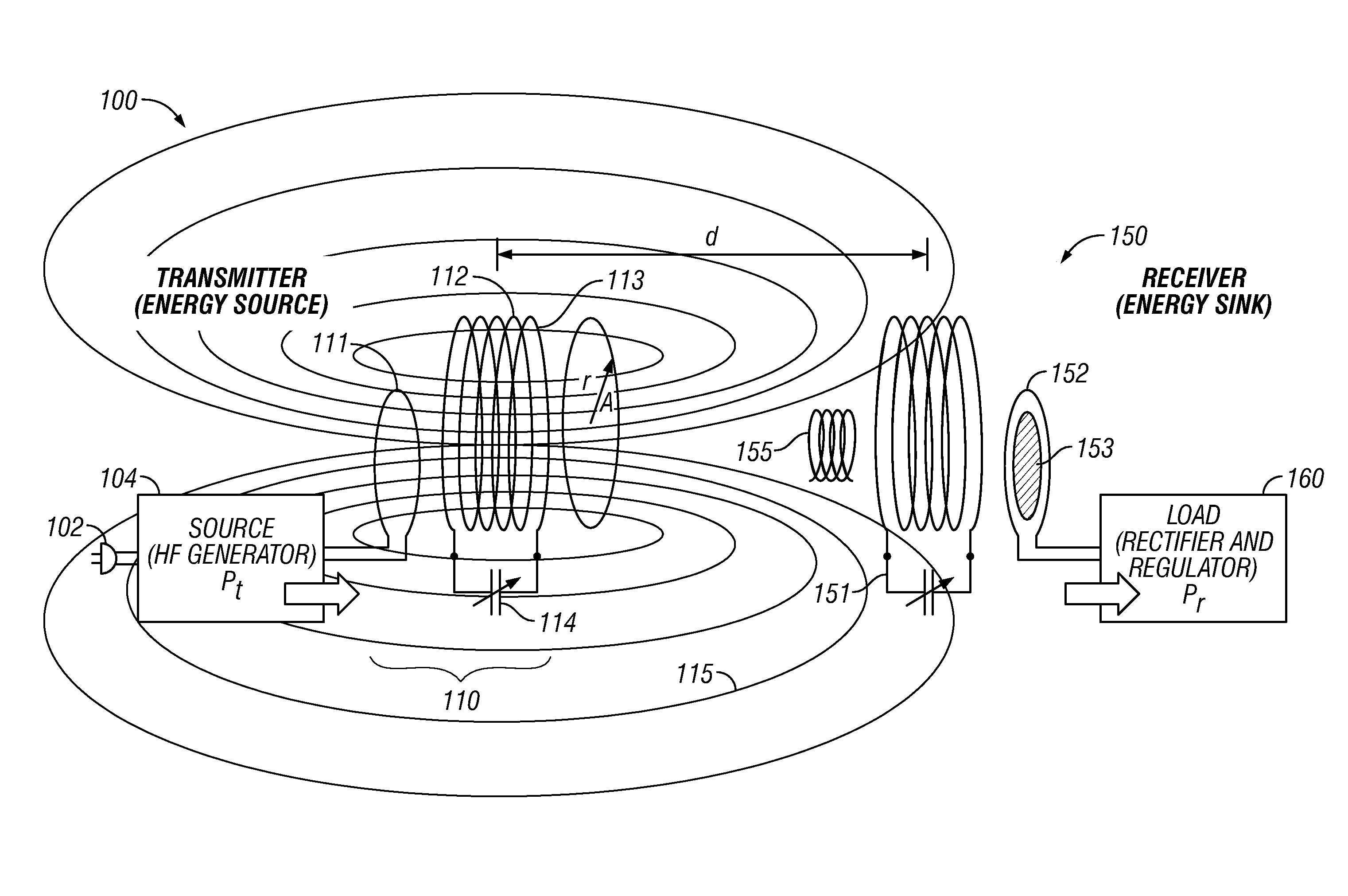
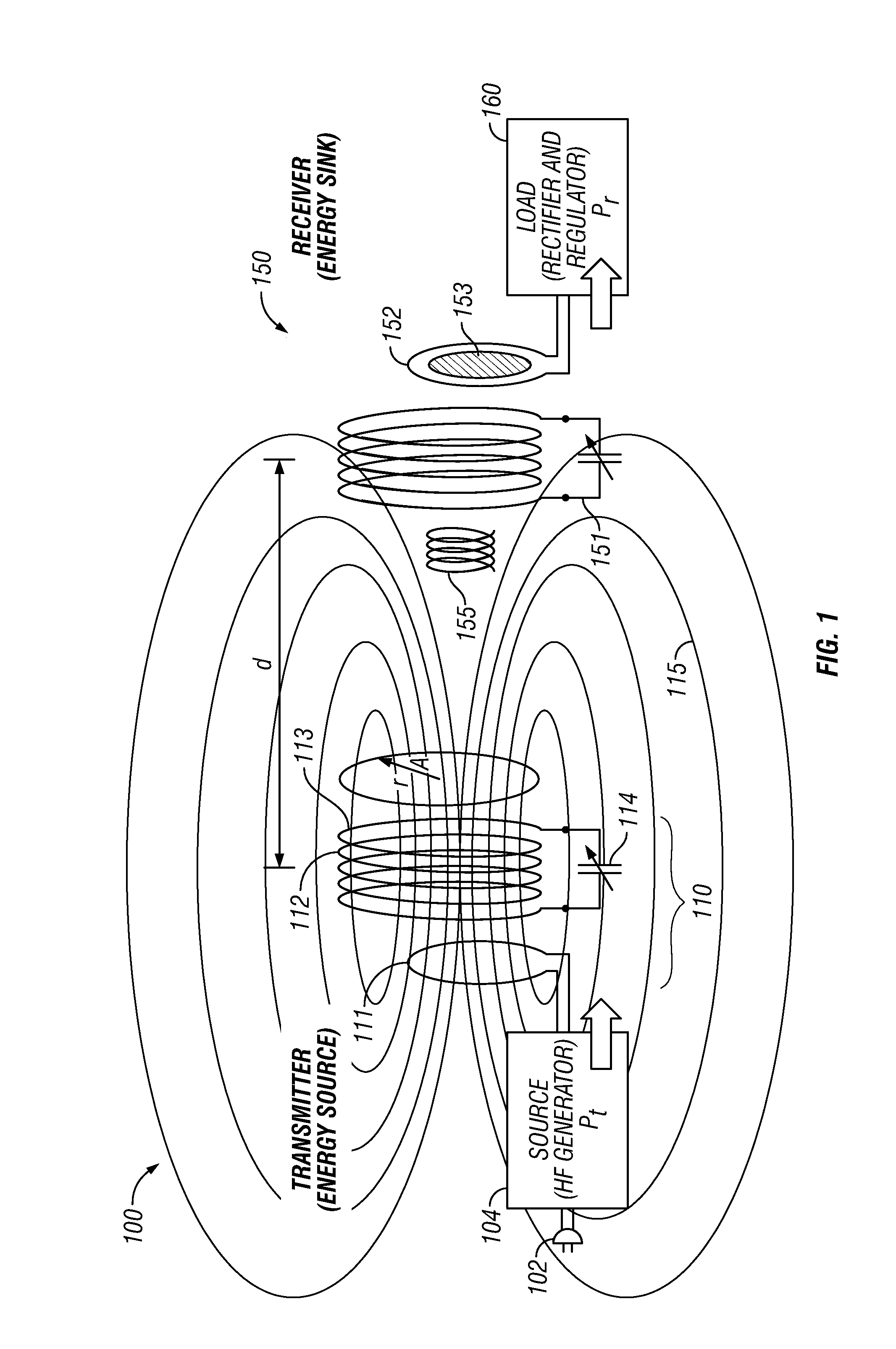
[0015]A basic embodiment is shown in FIG. 1. A power transmitter assembly 100 receives power from a source, for example, an AC plug 102. A frequency generator 104 is used to couple the energy to an antenna 110, here a resonant antenna. The antenna 110 includes an inductive loop 111, which is inductively coupled to a high Q resonant antenna part 112. The resonant antenna includes a number N of coil loops 113 each loop having a radius RA. A capacitor 114, here shown as a variable capacitor, is in series with the coil 113, forming a resonant loop. In the embodiment, the capacitor is a totally separate structure from the coil, but in certain embodiments, the self capacitance of the wire forming the coil can form the capacitance 114.

[0016]The frequency generator 104 can be preferably tuned to the antenna 110, and also selected for FCC compliance.

[0017]This embodiment uses a multidirectional antenna. 115 shows the energy as output in all directions. The antenna 100 is non-radiative, in th...


PUM


Abstract

Techniques for wireless power transmission at levels that induce high power transfer and/or high efficiency of coupling.

Description

[0001]This application claims priority from provisional application No. 60 / 973,166, filed Sep. 17, 2007, the entire contents of which disclosure is herewith incorporated by reference.BACKGROUND[0002]It is desirable to transfer electrical energy from a source to a destination without the use of wires to guide the electromagnetic fields. A difficulty of previous attempts has been low efficiency together with an inadequate amount of delivered power.[0003]Our previous applications and provisional applications, including, but not limited to, U.S. patent application Ser. No. 12 / 018,069, filed Jan. 22, 2008, entitled “Wireless Apparatus and Methods”, the entire contents of the disclosure of which is herewith incorporated by reference, describe wireless transfer of power.[0004]The system can use transmit and receiving antennas that are preferably resonant antennas, which are substantially resonant, e.g., within 5-10% of resonance, 15% of resonance, or 20% of resonance. The antenna(s) are pr...

Claims


Application Information

Patent Timeline
Patent Type & Authority Applications(United States)
IPC IPC(8): H02J17/00
CPCH02J17/00H01Q7/00H01Q1/2225H02J5/005H02J50/27H02J50/23H02J50/05H02J50/12H02J50/40H04B5/0037H01Q1/248H01F38/14
Inventor COOK, NIGEL P.SIEBER, LUKASWIDMER, HANSPETER
Owner QUALCOMM INC
Why Eureka
Try Eureka