Low side n-channel fet protection circuit

a protection circuit and low-side technology, applied in the direction of battery overheat protection, safety/protection circuit, instruments, etc., can solve the problems of increasing the cost, excessive charge, and most batteries generating hea

Active Publication Date: 2009-03-19
INT COMPONENTS
View PDF17 Cites 44 Cited by
  • Summary
  • Abstract
  • Description
  • Claims
  • Application Information

AI Technical Summary

Problems solved by technology

Furthermore, most batteries generate heat as they charge; for some type of batteries, excessive charge can pose a potential fire risk.
C...

Method used


Image

  • Low side n-channel fet protection circuit
  • Low side n-channel fet protection circuit
  • Low side n-channel fet protection circuit

Examples


first embodiment

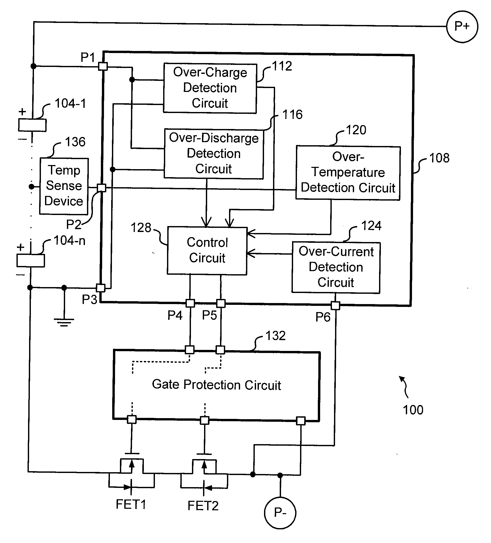
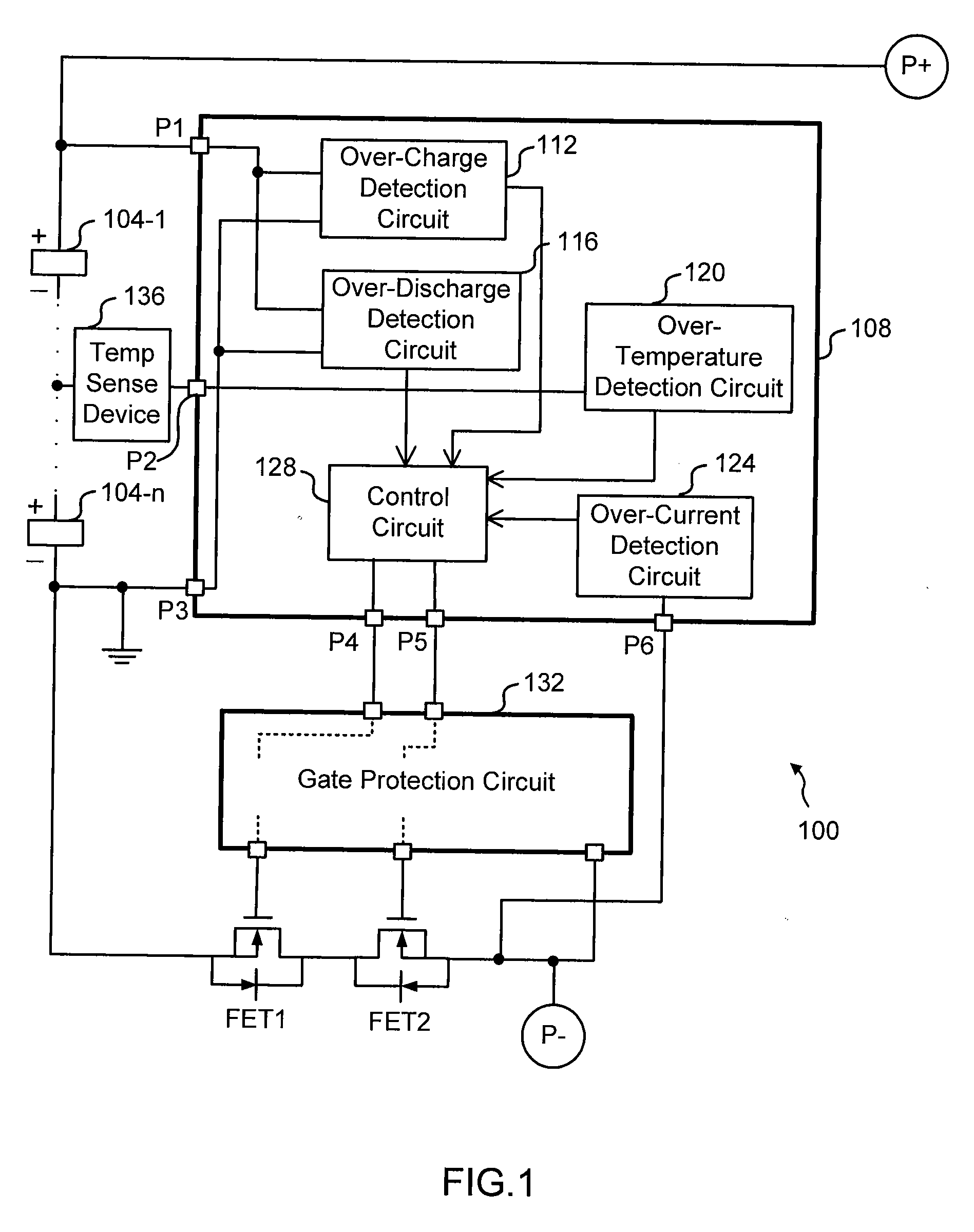
[0017]FIG. 1 is a block diagram showing a battery protection circuit 100 coupled to a plurality of batteries 104-1 through 104-n connected in series. P+ denotes a positive terminal, which is a connection point to an external device at the positive side of the battery pack; and P− denotes a negative terminal, which is a connection point to the external device at the negative side of the battery pack. When the batteries need to be recharged, a charger is attached to P+ and P−, and the charge current flows from P+ through the battery pack to P−. When a load is attached to P+ and P−, the battery pack sources energy to the load, and the discharge current flows from P+ through the load to P−. A controller 108 comprises an over-charge detection circuit 112, an over-discharge detection circuit 116, an over-temperature detection circuit 120, an over-current detection circuit 124 and a control circuit 128, and outputs control signals for controlling ON / OFF of the two N-channel MOSFETs (FET1 ...

second embodiment

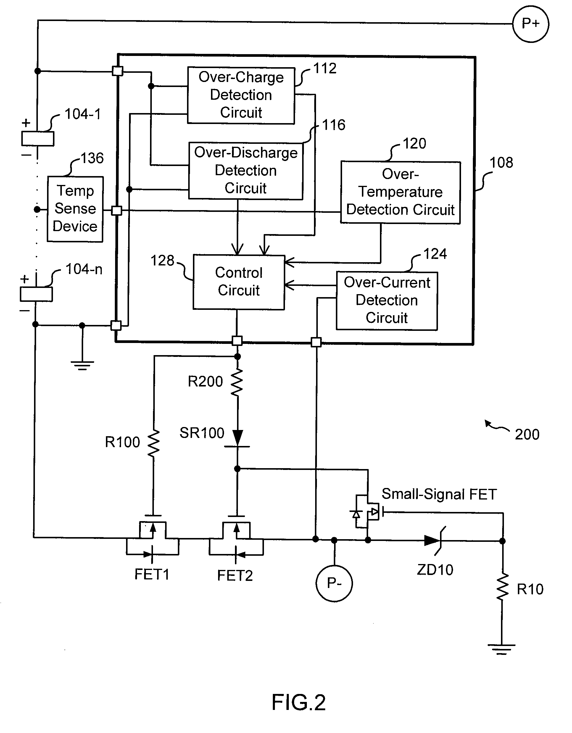
[0024]FIG. 2 is a block diagram showing a protection circuit 200 according to the present invention. A specific implementation of the gate protection circuit 132 is depicted. In this embodiment, the gate protection circuit 132 comprises three resistors R10, R100 and R200, one Schottky diode SR100, one Zener diode ZD10, and one small-signal FET. The resistor R10 is connected to the second ground. P− is connected to a point internal to the point where the small-signal FET is connected. The gates of FET1 and FET2 are coupled to the common output pin of the controller 108, receiving a control signal from the control circuit 128. Thus, ON / OFF of FET1 and FET2 is controlled by the same control signal from the single output pin in this embodiment. In another embodiment, the circuit is configured such that the two gates receive separate control signals from respective output pins to separately control ON / OFF of the two MOSFETs.

[0025]The voltage at the output pin (i.e. the output voltage of ...

fourth embodiment

[0035]FIG. 6 is a block diagram showing a battery protection circuit 600 according to the present invention. In this embodiment, the gate protection circuit 132 is integrated with various detection and control circuits on a same chip to provide a control IC 608. Thus, the battery protection circuit 600 comprises two discrete power MOSFETs (FET1 and FET2) and the control IC 608, resulting in reduced parts count.


PUM


Abstract

The present invention relates to a battery protection circuit for protecting a plurality of batteries connected in series. The battery protection circuit includes: a controller for monitoring the batteries and outputting control signals based on predetermined conditions associated with the batteries; a first N-channel MOSFET and a second N-channel MOSFET coupled in a common-drain configuration in a low-side path, wherein at least one of the first and second N-channel MOSFETs turns off in response to the control signal received from the controller when at least one of the predetermined conditions is detected; and a gate protection circuit for preventing gate-to-source voltages of the first and second N-channel MOSFETs from exceeding a predetermined gate-to-source voltage level.

Description

BACKGROUND OF THE INVENTION[0001]The present invention relates to a battery protection circuit having protection functions that turn off the current path when an abnormal condition occurs in a battery pack, in particular, but not by way of limitation, of a plurality of Lithium Sulfur (LiS) batteries connected in series.[0002]Lithium Sulfur (LiS) rechargeable batteries provide users with high-energy and light-weight solutions. For example, LiS batteries developed by Sion Power™ Corporation, Tucson Ariz., are reported to be capable of delivering a specific energy of 400 Wh / kg and an energy density of 425 Wh / liter. The specific energy of the LiS battery exceeds that of state-of-the-art Lithium Ion (Li Ion) chemistry by a factor of greater than two, while the energy density stands at an equivalent level. That is, a LiS battery provides the same runtime for a portable computer in less than half the weight, or twice the runtime in the same weight while having a volume comparable to a Lith...

Claims


Application Information

Patent Timeline
IPC IPC(8): H02J7/04
CPCH02J7/0031H02J7/00302H02J7/00309H02J7/00306H02J7/00304
Inventor IBRAHIM, RANDOLPH A.
Owner INT COMPONENTS
Why Eureka
Try Eureka