Power amplifier

a power amplifier and amplifier technology, applied in the direction of amplifier modifications to reduce non-linear distortion, digital transmission, baseband system details, etc., can solve the problems of unnecessary power loss generated in the distortion compensation method of the related art, drastic reduction of power efficiency, increased power consumption, etc., to reduce distortion, improve efficiency, and reduce distortion

Active Publication Date: 2009-03-19
NEC CORP
View PDF2 Cites 23 Cited by
  • Summary
  • Abstract
  • Description
  • Claims
  • Application Information

AI Technical Summary

Benefits of technology

[0019]The present invention was achieved for solving the problems of the above-described related art and has as an object the provision of a power amplifier that controls power loss and reduces distortion.
[0021]In the present invention, although third-order intermodulation distortion that is in-phase with the main signal is generated when the input signal is amplified in the second amplification path, the amplitude of this third-order intermodulation distortion is reduced by the anti-phase third-order intermodulation distortion that is generated by the anti-phase third-order intermodulation distortion generation circuit. In addition, the main signal supplied from the synthesizer is a signal amplified by each of the first amplifier and second amplifier. As a result, a reduction of distortion can be achieved while suppressing the power loss during power synthesis that was generated in the parallel low-distortion amplifiers of the related art. In addition, the present invention enables an amplifier that operates with higher efficiency and lower distortion.

Problems solved by technology

The first problem that is to be solved is the unnecessary power loss generated in the distortion compensation method of the related art.
For example, the need for error amplifier and delay circuits in the feed-forward amplifier referred to in FIG. 1 leads to the problem of increased power consumption.
In particular, a drastic reduction in power efficiency occurs because distortion ideally should not occur in the error amplifier and the error amplifier must therefore be made somewhat large, and moreover, because the error amplifier itself does not supply a main signal.
In addition, the occurrence of delay in the amplifier and error amplifier necessitates delay lines to implement satisfactory distortion compensation over a broad bandwidth.
In particular, the provision of the delay lines on the output side of the main amplifier causes the problem of a reduction of the overall efficiency of the amplifier due to the loss in these lines.
In the output synthesizer in the distortion compensation amplification device referred to in FIG. 2, a drop in power of the main signal occurs because the main signal is combined in an anti-phase state, and the drop in power results in power loss, and therefore, a reduction of the power efficiency.
The second problem to be solved is the occurrence of large signal distortion and the deterioration in linearity in the high-efficiency amplifier of the related art.

Method used


Image

  • Power amplifier
  • Power amplifier
  • Power amplifier

Examples


first exemplary embodiment

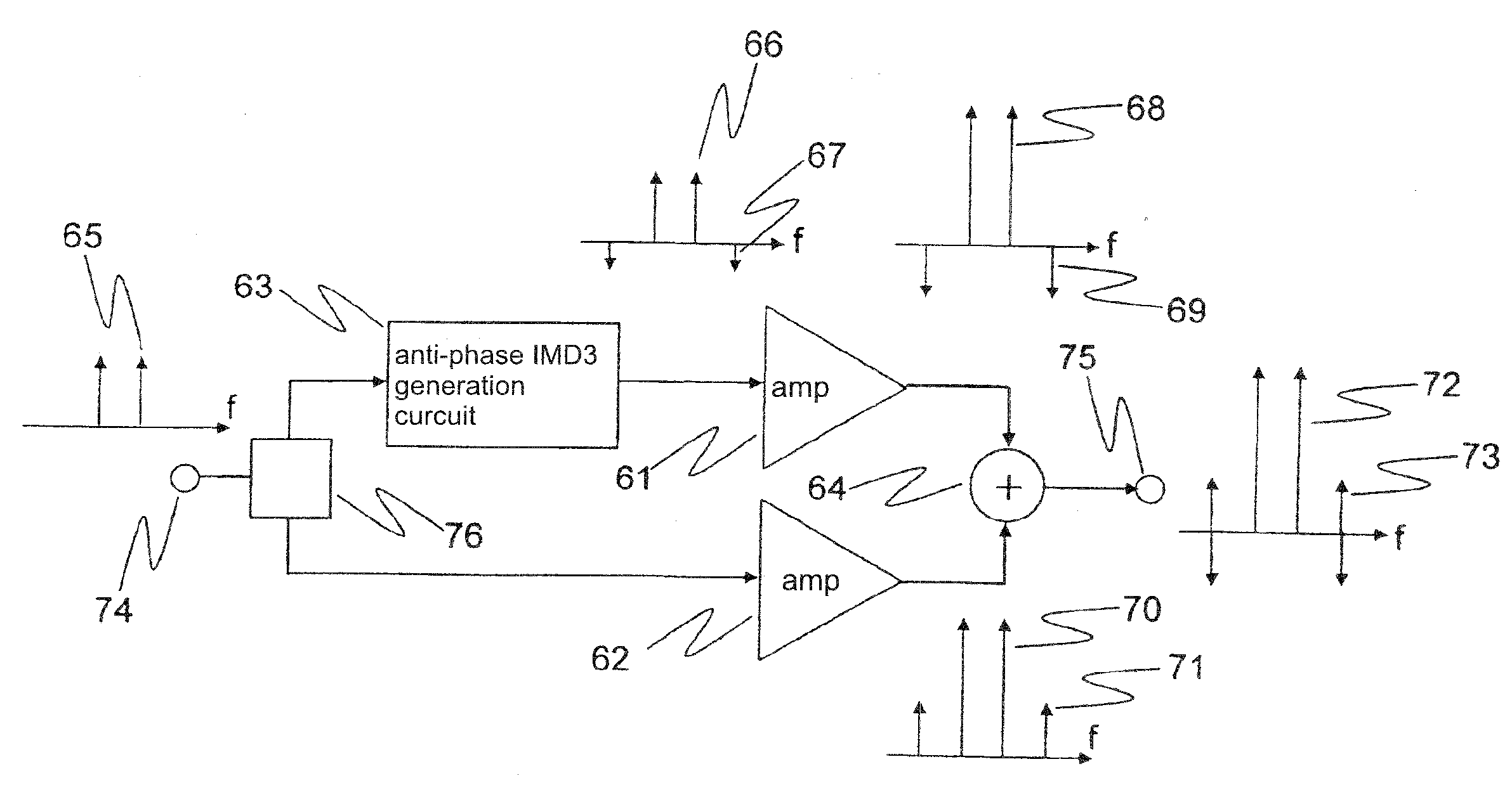
[0102]Explanation next regards the configuration of the power amplifier of the first exemplary embodiment of the present invention.

[0103]FIG. 4 is a block diagram showing an example of the configuration of the power amplifier according to the first exemplary embodiment. As shown in FIG. 4, the power amplifier of the present exemplary embodiment includes distributor 76 for distributing input signal 65, third-order intermodulation distortion generation circuit 63 for supplying main signal 66 and third-order intermodulation distortion (IMD3) 67 that is anti-phase with main signal 66, amplifier 61 connected to the output side of anti-phase third-order intermodulation distortion generation circuit 63, amplifier 62 connected in parallel to anti-phase third-order intermodulation distortion generation circuit 63 and amplifier 61, and synthesizer 64 for combining the output signals of amplifier 61 and amplifier 62. Input terminal 74 for receiving an input signal from the outside is provided ...

second exemplary embodiment

[0163]Explanation next regards the configuration of the power amplifier of the second exemplary embodiment of the present invention. FIG. 8 is a block diagram showing an example of the configuration of the power amplifier according to the second exemplary embodiment.

[0164]As shown in FIG. 8, the power amplifier of the present exemplary embodiment includes: distributor 76 for distributing an input signal, anti-phase IMD3 generation circuit 63 for supplying a main signal and a third-order intermodulation distortion that is anti-phase with the main signal, amplifier 61 that is connected to the output of the anti-phase IMD3 generation circuit 63, amplifier 62 that is connected in parallel with anti-phase IMD3 generation circuit 63 and amplifier 61, and synthesizer 64 that combines the output signals of amplifier 61 and amplifier 62. Input terminal 74 is provided in the section preceding distributor 76, and output terminal 75 is provided in the section after synthesizer 64. The details r...

third exemplary embodiment

[0259]Explanation next regards the configuration of the power amplifier according to the third exemplary embodiment of the present invention. The power amplifier of this exemplary embodiment is of a configuration in which two power amplifiers described in the first exemplary embodiment are connected in a series.

[0260]FIG. 27 is a block diagram showing an example of the configuration of power amplifier according to the third exemplary embodiment. As shown in FIG. 27, the power amplifier of the present exemplary embodiment is of a configuration that includes: low-distortion amplifier 481a to which a signal is applied as input and low-distortion amplifier 481b connected to a section that follows low-distortion amplifier 481a. Input terminal 74 is provided in a section before low-distortion amplifier 481a, and output terminal 75 is provided in a section following low-distortion amplifier 481b.

[0261]Low-distortion amplifier 481a includes: distributor 76a that distributes input signal 65...


PUM


Abstract

A power amplifier of the present invention includes a distributor (76) for distributing an input signal; an anti-phase third-order intermodulation distortion generation circuit (63) for, upon receiving the input signal that was distributed by the distributor, generating third-order intermodulation distortion for which the phase difference is anti-phase with respect to each of two main signals of different frequencies and supplying the two main signals and the third-order intermodulation distortion; a first amplifier (61) for amplifying the signal received from the anti-phase third-order intermodulation distortion generation circuit and supplying the result; a second amplifier (62) for amplifying the input signal that was distributed by the distributor and supplying the result; and a synthesizer (64) for combining the output signal of the first amplifier and the output signal of the second amplifier.

Description

TECHNICAL FIELD[0001]The present invention relates to a power amplifier used in radio communication.BACKGROUND ART[0002]In radio transmitters used for high-speed communication, high linearity (low distortion characteristic) is required in amplifiers to transmit data correctly. An explanation follows below regarding the configuration and operation of an amplifier of the related art.[0003]FIG. 1 is a block diagram showing a feed-forward amplifier for realizing a low-distortion characteristic. The feed-forward amplifier includes: amplifier 1, delay lines 10 and 11, subtractor 2 for synthesizing the signal from amplifier 1 and the signal from delay line 10 and extracting third-order intermodulation distortion 6, error amplifier 3 for amplifying third-order intermodulation distortion 6 to generate third-order intermodulation distortion 7, and synthesizer 4 for offsetting third-order intermodulation distortion 6 and third-order intermodulation distortion 7.[0004]As a simple explanation of...

Claims


Application Information

Patent Timeline
Patent Type & Authority Applications(United States)
IPC IPC(8): H03F1/32H03F3/68
CPCH03F1/3223
Inventor YAMANOUCHI, SHINGOKUNIHIRO, KAZUAKI
Owner NEC CORP
Why Eureka
Try Eureka