Image processing device and digital camera

a technology of image processing and digital camera, which is applied in the field of image processing device and digital camera, can solve the problems of deteriorating image quality by contraries, increasing the gain of a noise component in a pixel whose gain is increased through visual processing, and remarkable noise components, so as to restore resolution which is already deteriorated

Active Publication Date: 2009-03-19
PANASONIC SEMICON SOLUTIONS CO LTD
View PDF6 Cites 24 Cited by
  • Summary
  • Abstract
  • Description
  • Claims
  • Application Information

AI Technical Summary

Benefits of technology

[0012]The present invention was made in view of the above problems. An object of the present invention is to enable visual processing to be performed on a pixel-by-pixel basis while deterioration of an image is prevented.
[0015]In this way, it is possible to restore the resolution which is already deteriorated before the visual processing or to correct characteristics of image data which are deteriorated due to the visual processing.

Problems solved by technology

However, in the image processing device of Patent Document 1, when image data whose luminance value has a wide dynamic range is subjected to visual processing, a gain of a noise component in a pixel whose gain is increased through the visual processing is also increased.
As a result, in the corrected image data, the noise component can be remarkable.
That is, performing the visual processing may deteriorate the image quality by contraries.
As a result, the area corresponding to the person becomes bright, but a gain of a noise component in the area corresponding to the person is also increased.
Therefore, if luminance values of pixels in a block have a wide dynamic range, the effect of histogram equalization may be too strong or insufficient in some of the pixels.
Moreover, if the noise reduction processing is performed with a uniform strength on all the pixels in a block, noise in pixels having a number of noise components may not be sufficiently suppressed, or by contraries, an edge of an area having a small amplitude of noise may become dull.
However, as the block size decreases, the amount of data which has to be processed to determine the histogram increases.
That is, a reduction of the block size has a limit, and thus it is difficult to realize both appropriate visual processing and suppression of noise (prevention of image deterioration).

Method used


Image

  • Image processing device and digital camera
  • Image processing device and digital camera
  • Image processing device and digital camera

Examples


embodiment 1

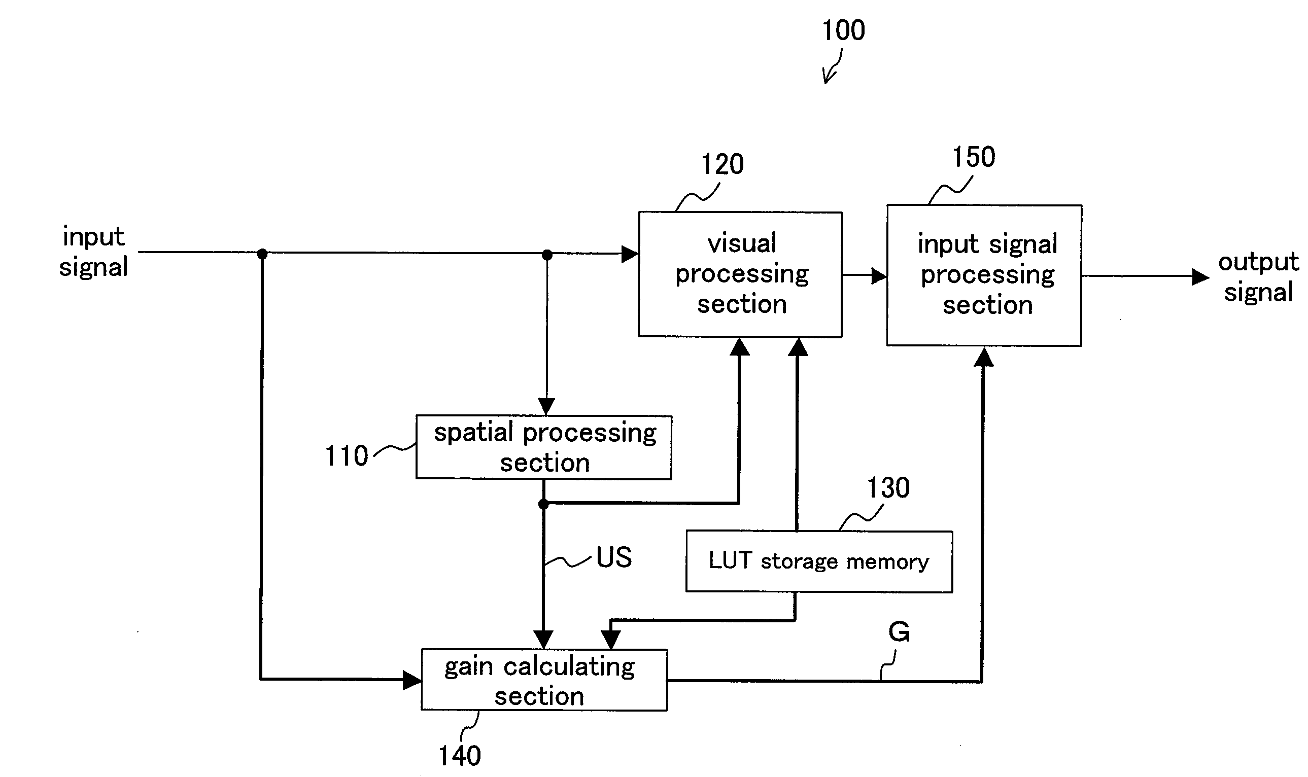
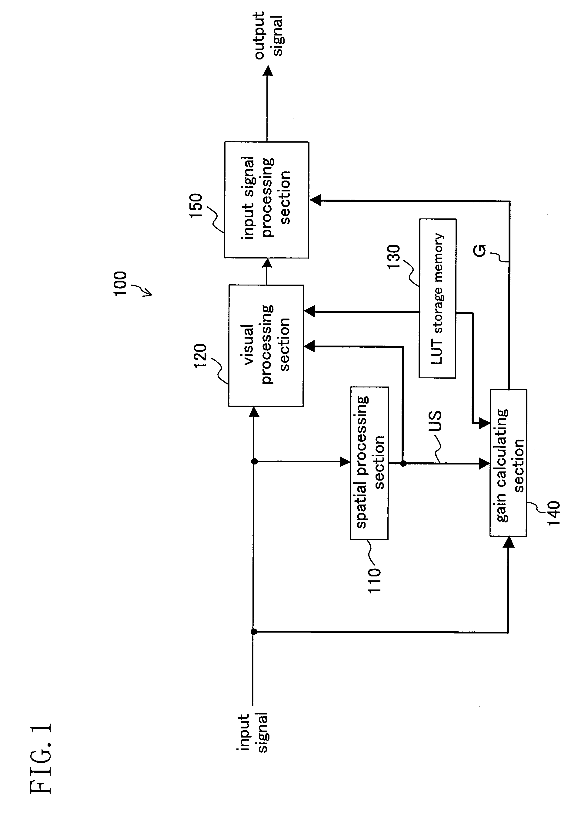
[0036]FIG. 1 is a block diagram showing a configuration of an image processing device 100 according to Embodiment 1 of the present invention. The image processing device 100 is incorporated in, for example, a digital camera to perform signal processing based on human visual characteristics on respective pixels constituting image data.

[0037](Configuration of Image Processing Device 100)

[0038]As shown in FIG. 1, the image processing device 100 includes a spatial processing section 110, a visual processing section 120, a LUT storage memory 130, a gain calculating section 140, and an input signal processing section 150.

[0039]The spatial processing section 110 generates a signal showing distribution of signal levels of surrounding pixels around a pixel under processing(referred to as a signal level distribution signal). In the present embodiment, as an example of the signal level distribution signal, the spatial processing section 110 generates an unsharp signal US on a pixel-by-pixel ba...

embodiment 2

[0088]FIG. 11 is a block diagram showing a configuration of an image processing device 200 according to Embodiment 2 of the present invention. The image processing device 200 is also incorporated in, for example, a digital camera, or the like and performs signal processing based on human visual characteristics on respective pixels constituting an image.

[0089]The image processing device 200 is an example of an image processing device in which before the signal processing is performed, processing to restore the resolution of an input signal is performed.

[0090]In the image processing device 200, aperture correction processing, which is one of processing to restore the resolution is performed. A high frequency component of the input signal input through a lens or an optical low-pass filter is dull. The aperture correction processing is correction processing in which the input signal input with its high frequency component being dull is processed such that the high frequency component is...

embodiment 3

[0114]In Embodiment 3, an example of a digital camera including the image processing device mentioned above is described. FIG. 16 is a block diagram showing a configuration of a digital camera 300 according to the present embodiment. As shown in the figure, the digital camera 300 includes an image processing device 100 (see Embodiment 1), an imaging section 310, an input signal selector 320, a display section 330, a compression conversion section 340, and a recording and saving section 350.

[0115]The imaging section 310 captures an image of an object and outputs digital image 20 data corresponding to the image. In this example, the imaging section 310 includes an optical system 311, an image sensor 312, an analog front end 313 (in the figure, abbreviated as AFE), and a timing generator 314 (in the figure, abbreviated as TG).

[0116]The optical system 311 includes a lens or the like and forms the image of the object on the image sensor 312. 25 The image sensor 312 converts light enterin...


PUM


Abstract

A visual processing section 120 is provided which performs visual processing on a pixel-by-pixel basis according to a predetermined function defining a relation between a pixel value of a target pixel which is a pixel under visual processing and a pixel value of the target pixel after subjected to the visual processing. An input signal processing section 150 is further provided which performs, on a pixel-by-pixel basis, at least one of signal processing to restore resolution of an image data input to the visual processing section 120 and signal processing to correct signal deterioration due to the visual processing. In the input signal processing section 150, the at least one signal processing is performed according to a gain determined by using the function.

Description

BACKGROUND OF THE INVENTION[0001]1. Field of the Invention[0002]The present invention relates to an image processing device for performing signal processing based on human visual characteristics in an imaging device such as a digital camera, the signal processing being compression of a dynamic range, gray level correction, contrast enhancement, or the like.[0003]2. Description of the Prior Art[0004]When an image of a person is captured under a backlight condition by an imaging device such as a digital camera, image data obtained by capturing the image includes luminance information of a wide dynamic range from a dark portion to a bright portion. Therefore, some of imaging devices such as digital cameras include an image processing device for correcting such image data to have appropriate image quality.[0005]As an example of such an image processing device, known is an image processing device adopting a visual processing technique, wherein according to luminance distribution of surro...

Claims


Application Information

Patent Timeline
Patent Type & Authority Applications(United States)
IPC IPC(8): H04N5/228G06K9/40
CPCH04N1/58H04N5/142H04N5/20H04N9/646H04N5/21H04N5/243H04N5/208H04N23/76
Inventor OGAWA, MAYUYAMAMOTO, YASUTOSHITANIZOE, YUKIHIRO
Owner PANASONIC SEMICON SOLUTIONS CO LTD
Why Eureka
Try Eureka